Airplane Parts — Components and Structure of an Aircraft Explained
Understanding the Fundamental Architecture of an Aircraft
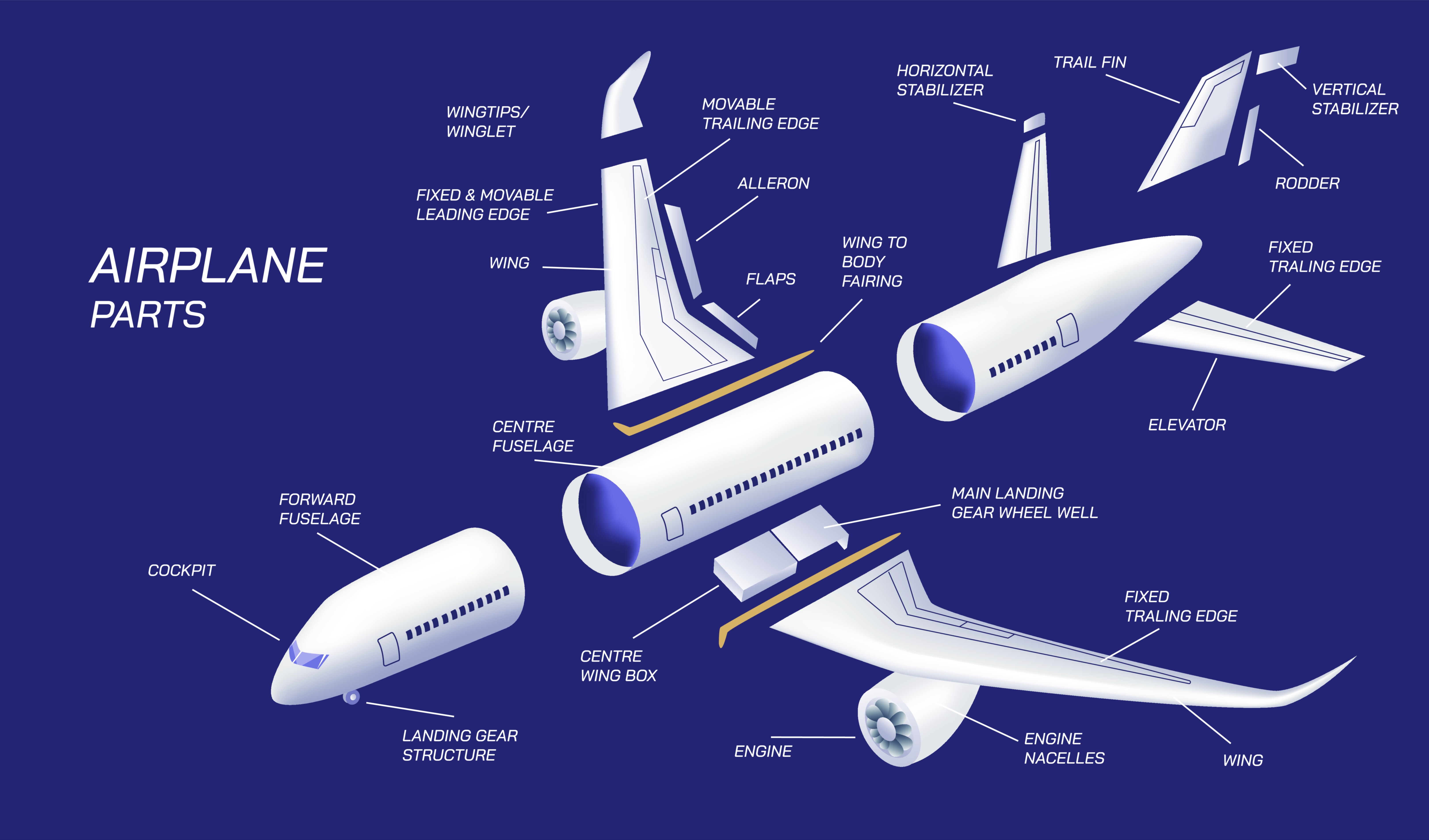
The structure of an airplane is a harmonious integration of mechanical, aerodynamic, and structural systems that together allow a machine to fly, maneuver, and transport passengers or cargo safely through the sky. Every part of an aircraft serves a specific purpose, contributing either to lift generation, stability, propulsion, control, safety, or the structural integrity needed to withstand aerodynamic forces. While all airplanes share common foundational components, their design and configuration vary depending on mission requirements, speed range, operational environment, and performance demands. A vector illustration showing aircraft parts typically provides a clear visual breakdown of how these components fit together, helping viewers understand the essential construction of a modern airplane. From nose cone to tail assembly, and from landing gear to wings, each component reflects decades of engineering evolution that balances strength, efficiency, aerodynamics, and safety. Understanding how these parts interact offers a window into the sophisticated science behind aviation and the remarkable engineering that enables sustained, controlled human flight.
Fuselage — The Central Structural Body
The fuselage is the long, cylindrical body of the aircraft that houses the cockpit, passenger cabin, cargo holds, avionics compartments, and structural attachment points for wings and tail surfaces. It acts as the core structural backbone, distributing loads between all major sections and ensuring the aircraft remains rigid yet lightweight. Pressurized fuselages found in commercial jets must withstand significant internal pressure at high altitudes while also handling aerodynamic forces generated during flight. Their construction typically involves aluminum alloys, composite materials, or advanced carbon-fiber reinforced structures that balance durability with weight reduction. Internally, the fuselage integrates wiring systems, climate control ducts, fuel lines, and structural frames that maintain shape and support cabin amenities. A vector illustration often labels the cockpit windows, front nose section, main cabin doors, and belly cargo bays, giving a clear sense of how the fuselage supports both passenger comfort and aerodynamic efficiency.
Wings — The Primary Lift-Generating Structures
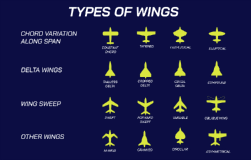
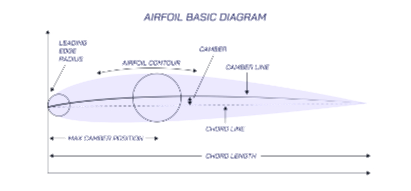
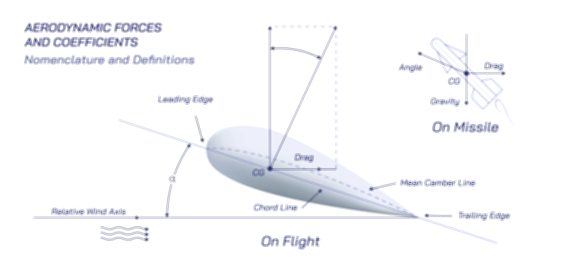
Wings are the defining feature of any fixed-wing aircraft, responsible for creating the lift that supports the plane against gravity. Their internal structure consists of spars, ribs, stringers, and skin panels that work together to maintain airfoil shape and withstand bending forces during flight. The wing’s airfoil profile is carefully engineered to manipulate airflow: air moves faster over the curved upper surface, reducing pressure and generating lift. Wings also host a wide array of high-lift devices—including flaps, slats, spoilers, and ailerons—that enhance control and performance during takeoff, landing, and maneuvering. Fuel tanks are commonly integrated into the wing structure, allowing efficient weight distribution and freeing space within the fuselage. Depending on aircraft design, wings may be straight, swept, delta-shaped, or tapered, each optimized for specific speed regimes and aerodynamic behavior. In vector illustrations, wings are often shown with labeled control surfaces to help viewers visualize how airflow and lift are managed across the span.
Tail Assembly (Empennage) — Stability and Control in Flight
The empennage, or tail section, ensures the aircraft maintains stability and responds predictably to control inputs. It typically consists of a vertical stabilizer with a rudder and horizontal stabilizers with elevators. The vertical stabilizer prevents unwanted yawing motion—side-to-side nose movement—and the rudder allows the pilot to control this axis. The horizontal stabilizer, usually located at the rear, prevents excessive pitching and maintains a level attitude, while the elevators adjust the aircraft’s nose angle during climb or descent. Some aircraft use a T-tail configuration where the horizontal stabilizer is mounted atop the vertical fin, while fighter jets or experimental planes may incorporate canards in place of traditional tailplanes. In vector illustrations, the empennage is typically shown with the rudder and elevators highlighted as movable surfaces, illustrating the essential role these components play in maintaining aerodynamic balance and maneuverability.
Engines and Propulsion Systems — Producing Thrust for Forward Motion
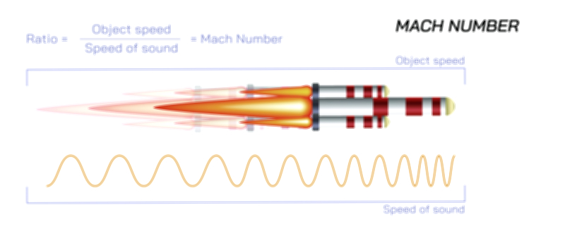
Aircraft propulsion relies on engines that generate thrust to overcome drag and maintain forward motion. Jet engines—turbofans, turbojets, or turboprops—dominate modern commercial and military aviation because of their efficiency and power at high speeds. Turbofan engines combine a large front fan with a gas turbine core, delivering high thrust while reducing noise and fuel consumption. Propeller-driven aircraft rely on piston engines or turboprops that rotate blades, accelerating air backward to push the aircraft forward. Engine placement varies based on design: under-wing mounts improve aerodynamics and facilitate maintenance, rear-mounted engines reduce cabin noise, and fighter jets may bury engines in the fuselage for improved stealth and airflow. Vector illustrations often show engine nacelles, air intakes, exhaust nozzles, and fan blades to emphasize how thrust is produced and directed. Understanding propulsion systems is crucial because engines directly influence performance, climb rate, cruising speed, and overall fuel efficiency.
Landing Gear — Supporting the Aircraft on the Ground
The landing gear system consists of wheels, shock absorbers, struts, and brakes that support the aircraft during takeoff, landing, and taxiing. It must endure tremendous forces as the aircraft impacts the runway at high speeds. Most airplanes use tricycle landing gear, consisting of a nose wheel and two main gear assemblies beneath the wings or fuselage. These systems retract into the aircraft during flight to reduce drag. Commercial jet landing gear typically features multiple wheels on each strut to distribute weight and enhance braking power, especially for heavy aircraft. Shock-absorbing oleo struts cushion landing forces, while hydraulic brakes slow the aircraft after touchdown. Vector illustrations often depict the landing gear extended and retracted to demonstrate its mechanism and interaction with other aircraft structures. Without a robust landing gear system, even the most advanced aircraft could not safely transition between ground and air.
Cockpit and Avionics — The Control Center of the Aircraft
The cockpit houses the pilots and the full suite of instruments and controls needed to operate the aircraft. Modern cockpits rely heavily on digital avionics such as flight management systems, primary flight displays, navigation computers, radar screens, and autopilot controls. These systems provide real-time information on altitude, speed, engine performance, orientation, weather conditions, and potential obstacles. Advanced aircraft also use fly-by-wire systems where pilot inputs are interpreted electronically rather than through direct mechanical linkages. The cockpit’s design emphasizes ergonomics, visibility, and human-machine interaction to ensure pilots can operate the aircraft safely under a range of conditions. Vector illustrations of cockpit components typically identify control yokes or joysticks, throttle levers, instrument panels, and overhead panels, showing how pilots interact with the aircraft’s internal systems.
Fuel Systems, Electrical Systems, and Internal Structures
An aircraft also contains complex internal systems that operate largely behind the scenes. Fuel systems store, pump, and manage fuel across multiple tanks—often integrated into the wings—to maintain balance and ensure reliable engine feeding. Electrical systems power everything from lighting and instrumentation to hydraulic pumps and in-flight entertainment. Hydraulic and pneumatic systems operate landing gear, control surfaces, braking systems, and thrust reversers. The internal structural framework, made of ribs, frames, and stringers, gives the aircraft strength while keeping weight to a minimum. These systems work together seamlessly to support safe flight, even though passengers rarely see them directly.
Illustrating Aircraft Components Through Vector Graphics
A vector illustration depicting airplane parts typically presents a clean, labeled breakdown of major components such as the fuselage, wings, engines, cockpit, tail assembly, and landing gear. Additional internal diagrams may highlight spars within wings, frames inside the fuselage, and control surface placement. Arrows often indicate motion—such as rudder deflection or flap extension—while simplified airflow lines show how the wings interact with the atmosphere. These visuals provide an intuitive understanding of aircraft architecture, making it easier to grasp how each part contributes to stability, lift, control, propulsion, and structural strength.