Airfoil Basic Diagram — Lift Generation and Aerodynamic Flow
Understanding the Shape and Purpose of an Airfoil
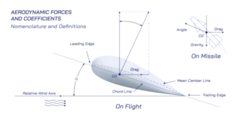
An airfoil is the foundational aerodynamic shape that makes sustained flight possible, serving as the structural and functional core of every aircraft wing, helicopter rotor, and many wind turbine blades. At its essence, an airfoil is designed to manipulate airflow in such a way that lift is generated efficiently, reliably, and with minimal energy loss. Its characteristic shape—curved on the top surface with a gentler curvature or flatter profile on the underside—creates a predictable pattern of air movement that affects pressure distribution around the wing. The smooth curvature, known as camber, allows air to accelerate over the upper surface while moving more slowly underneath, establishing the pressure differential essential for lift. The airfoil’s leading edge initiates smooth airflow, while the trailing edge allows air streams to rejoin with minimal turbulence. This carefully engineered form transforms an otherwise ordinary structure into a powerful aerodynamic tool capable of carrying enormous mass through the air. A basic diagram of an airfoil usually highlights these key features, showing the chord line, camber line, leading and trailing edges, and the surrounding airflow patterns that define aerodynamic performance.
How Lift Emerges from Airflow and Pressure Differences
Lift generation around an airfoil is governed by the interaction between airflow speed and pressure distribution, which together rely on fundamental aerodynamic principles. As air approaches the leading edge, the shape of the airfoil forces the upper stream to travel a longer path than the lower stream. The curvature causes the flow above the wing to accelerate, reducing pressure according to general airflow behavior, while the slower-moving air beneath maintains a relatively higher pressure. This pressure difference pushes the wing upward, creating lift. However, it is not only the curvature but also the angle of attack—the tilt of the airfoil relative to the oncoming air—that determines how this pressure differential evolves. Increasing the angle of attack increases lift up to a critical limit, after which airflow can no longer remain attached to the surface, causing a stall. In a basic airfoil diagram, airflow lines are shown bending smoothly over the upper surface and arcing under the bottom surface, visually demonstrating how the shape manipulates the air to produce lift. These lines help explain how even subtle changes in geometry can dramatically influence the magnitude and stability of lift.
The Role of Angle of Attack and Flow Attachment in Aerodynamic Performance
The angle at which the airfoil meets the incoming airflow has an enormous effect on lift generation. At low angles of attack, the airfoil produces moderate lift with minimal drag, maintaining smooth airflow from leading edge to trailing edge. As the angle increases, the lift grows because the airfoil deflects more air downward, a phenomenon directly related to momentum transfer as much as pressure distribution. This deflection reinforces the aerodynamic forces that keep the aircraft aloft. However, there is a critical angle of attack beyond which airflow cannot remain attached to the upper surface. Once separation occurs, a turbulent wake forms behind the airfoil, causing a dramatic drop in lift and a sharp rise in drag—a condition known as aerodynamic stall. A basic airfoil illustration often highlights these attached and separated flow patterns, emphasizing the boundary layer behavior and how airflow can transition abruptly from smooth laminar motion to chaotic turbulence. This visualization underscores the delicate balance between lift production and flow stability that pilots must manage during takeoff, landing, and maneuvering.
The Chord Line, Camber, and Thickness Distribution of an Airfoil
To fully understand airfoil function, one must consider its geometric components. The chord line is the straight line connecting the leading edge to the trailing edge, serving as a reference for both shape and angle of attack. The camber line, positioned midway between the upper and lower surfaces, indicates the curvature of the airfoil and plays a crucial role in determining lift characteristics. A highly cambered airfoil produces significant lift at low speeds, which is ideal for gliders, light aircraft, and slow-flying vehicles. In contrast, airfoils with flatter camber profiles are better suited for high-speed flight because they create less drag. Thickness distribution—the variation in cross-sectional thickness along the chord—affects structural strength, drag, and fuel efficiency. A typical vector illustration shows these geometric lines clearly, allowing learners to visualize how differences in camber or chord length alter aerodynamic behavior. This geometric understanding reveals how designers optimize airfoils for specific applications, balancing lift, drag, and structural requirements.
Boundary Layer Behavior and Its Influence on Lift and Drag
The boundary layer, a thin sheet of air closely adhering to the surface of the airfoil, plays a crucial role in aerodynamic efficiency. Within this narrow region, airflow transitions from nearly zero velocity at the surface to free-stream velocity just a short distance above it. Depending on conditions, the boundary layer can be either laminar—smooth and orderly—or turbulent, characterized by swirling energy and mixing. Laminar flow produces less drag but is prone to early separation, while turbulent flow generates more drag but adheres better to the airfoil’s contour, delaying stall. Aircraft designers often manipulate boundary layer behavior using various techniques, such as smoothing surfaces, installing vortex generators, or optimizing curvature to maintain attached flow. A vector illustration can show the boundary layer as a thin film hugging the airfoil, with arrows indicating velocity gradients and regions prone to separation. Understanding this phenomenon is essential for interpreting how lift and drag vary across different speeds, wing shapes, and atmospheric conditions.
Aerodynamic Flow, Downwash, and Newtonian Momentum Concepts
While pressure differences provide an elegant explanation for lift, Newtonian mechanics offer an equally important perspective: the wing generates lift by pushing air downward. As the airfoil moves forward, it deflects air toward the ground, creating a downward reaction force that produces upward lift in return. This downward movement of air, called downwash, intensifies behind the wing and extends far into the wake. Airfoil diagrams often highlight this downward flow, showing how the trailing edge angles airflow downward as part of the overall lift mechanism. This perspective shows that lift is not solely due to pressure differences but also to the redirection of airflow caused by the airfoil’s shape and orientation. A complete understanding of airfoil aerodynamics requires integrating both approaches, recognizing that pressure patterns and momentum transfer are complementary components of the same physical process.
Illustrating Airfoil Aerodynamics Through Vector Diagrams
A basic vector illustration of an airfoil typically presents a clean cross-sectional profile with labeled components such as the leading edge, trailing edge, chord line, and camber. Flow lines arching smoothly over the upper surface and gently under the lower surface help depict how lift is created. Additional elements may include arrows showing pressure gradients, angle-of-attack indicators, stagnation points where airflow splits, and regions where boundary layer separation occurs. Some diagrams extend to illustrate downwash and the overall aerodynamic force vectors acting on the airfoil. These visual tools clarify the interplay between shape, airflow, and lift, translating aerodynamic theory into intuitive graphical form that helps students, engineers, and enthusiasts appreciate the elegant mechanics of flight.