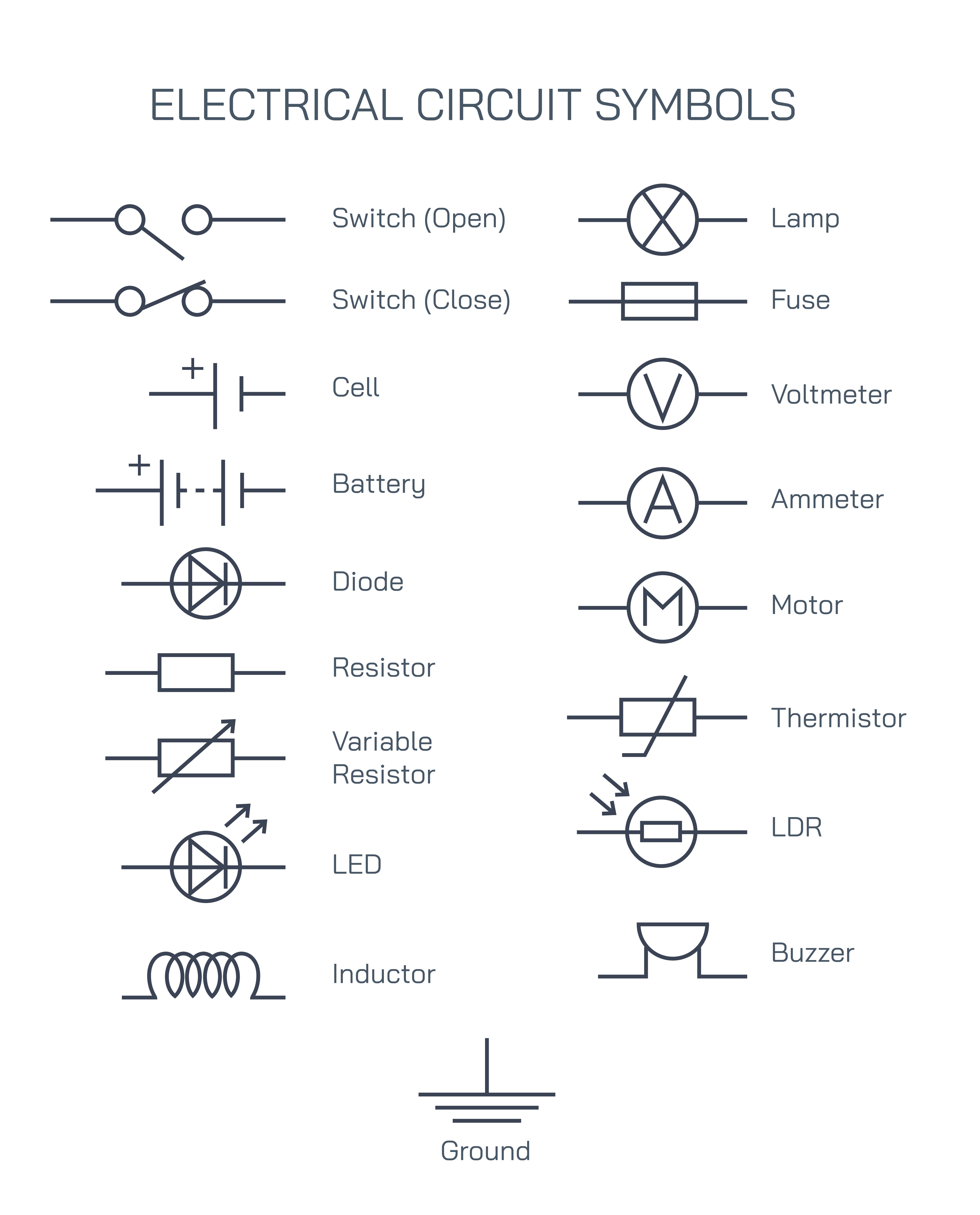
Standard electrical circuit symbols are universally accepted graphical representations used to depict electrical and electronic components in circuit diagrams. These symbols form the visual language of electricity and electronics, allowing engineers, technicians, students, and scientists to communicate circuit designs clearly and efficiently. Instead of drawing realistic pictures of components, standardized symbols provide a simplified and consistent method to represent complex electrical systems. Understanding these symbols is fundamental for reading, designing, and analyzing electrical and electronic circuits.
Purpose of Standard Electrical Circuit Symbols
Electrical circuits can range from very simple arrangements to extremely complex systems involving hundreds of components. Drawing detailed images of every component would make circuit diagrams cluttered and difficult to understand. Standard electrical symbols solve this problem by using simple shapes and lines to represent components. These symbols reduce confusion, save time, and ensure that circuit diagrams can be interpreted correctly anywhere in the world.
Standardization is essential because electrical systems often involve collaboration between people from different regions and disciplines. When everyone follows the same symbolic conventions, circuit diagrams become a universal language that transcends spoken languages.
Power Supply Symbols
Power supply components provide electrical energy to a circuit. The most basic power supply symbol is the cell, which represents a single source of electrical energy. A battery symbol represents multiple cells connected together to provide higher voltage. These symbols indicate the positive and negative terminals, which are crucial for understanding current direction and polarity in a circuit.
Power supply symbols help identify where electrical energy enters the circuit and serve as reference points for voltage levels throughout the system.
Switch Symbols and Their Significance
Switches control the flow of electric current by opening or closing a circuit. A switch open symbol represents a break in the circuit, indicating that current cannot flow. A switch closed symbol shows a continuous path, allowing current to pass. Switch symbols are essential for understanding how circuits are controlled manually or automatically.
Switches are used in almost all electrical systems, from household lighting to industrial machinery. Their symbols clearly show whether a circuit is intended to be normally on or normally off.
Load and Output Device Symbols
Load devices consume electrical energy and convert it into other forms such as light, heat, sound, or mechanical motion. The lamp symbol represents a light-emitting component used in basic circuits. The motor symbol represents a device that converts electrical energy into mechanical energy. The buzzer symbol represents a sound-producing device used in alarms and indicators.
These symbols allow designers to quickly identify how electrical energy is being used within a circuit and what output is expected.
Resistance and Control Component Symbols
Resistance is a fundamental property in electrical circuits. The resistor symbol represents a component that limits current flow. A variable resistor symbol shows a resistor whose resistance can be adjusted, allowing control over current or voltage in the circuit. A thermistor symbol represents a temperature-dependent resistor, commonly used in temperature sensing and control applications.
An LDR symbol represents a light-dependent resistor, whose resistance changes with light intensity. These control components are essential in automation, sensing, and regulation systems.
Diode and Semiconductor Symbols
Diodes are semiconductor devices that allow current to flow in one direction only. The diode symbol clearly indicates the permitted direction of current flow. The LED symbol represents a light-emitting diode, which emits light when current flows through it. LEDs are widely used in displays, indicators, and lighting systems due to their efficiency and durability.
These symbols are crucial in understanding circuit protection, signal control, and electronic functionality.
Measurement Instrument Symbols
Measurement devices are used to monitor electrical quantities within a circuit. The ammeter symbol represents a device that measures electric current. It is typically connected in series with the component being measured. The voltmeter symbol represents a device that measures voltage and is usually connected in parallel across a component or power source.
These symbols help identify testing and monitoring points within a circuit and are vital for troubleshooting and analysis.
Protection and Safety Symbols
Safety components protect circuits and users from damage and hazards. The fuse symbol represents a safety device that breaks the circuit when current exceeds safe limits. This prevents overheating, fires, and equipment damage. The ground symbol represents a reference point in the circuit that is connected to the Earth or a common return path. Grounding improves safety and stabilizes voltage levels.
Understanding protection symbols is critical for designing safe electrical systems.
Inductor Symbol and Energy Storage
The inductor symbol represents a coil of wire that stores energy in a magnetic field when current flows through it. Inductors are used in filters, transformers, and energy storage applications. They play a key role in alternating current circuits and power electronics.
Recognizing inductor symbols helps in understanding circuits involving magnetic effects and energy transfer.
Importance of Standardization in Circuit Symbols
Standard electrical symbols are governed by international standards to ensure consistency and accuracy. This standardization allows electrical diagrams to be understood globally without ambiguity. It also reduces errors during installation, maintenance, and repair of electrical systems.
In education, standardized symbols help students learn electrical concepts systematically. In industry, they enable efficient communication between designers, technicians, and engineers.
Educational and Practical Value
Learning standard electrical circuit symbols is one of the first steps in studying electricity and electronics. These symbols form the foundation for reading schematic diagrams, understanding circuit operation, and building real-world electrical systems. From school-level physics to advanced engineering design, circuit symbols remain essential tools.
Practical applications include household wiring, electronic device design, industrial automation, power distribution, and communication systems. Every electrical blueprint relies on these symbols to convey information accurately.
Conclusion
Standard electrical circuit symbols are the building blocks of electrical and electronic communication. They provide a clear, simple, and universal way to represent components and their connections in circuit diagrams. Symbols for power supplies, switches, loads, resistors, semiconductors, measuring instruments, and safety devices allow complex systems to be understood at a glance. Mastering these symbols is essential for anyone involved in electricity, electronics, physics, or engineering, as they form the foundation of circuit design, analysis, and safe electrical practice.