The ladder diagram is one of the most important and widely used graphical representations in electrical control systems and industrial automation. It visually represents the logic of control circuits in a form that resembles the rungs of a ladder, making it intuitive and easy to understand for electricians, technicians, and engineers. Ladder diagrams are extensively used in motor control circuits, relay-based systems, and programmable logic controller control programs. Understanding ladder diagrams is essential for anyone studying electrical engineering, industrial automation, or control systems.
What Is a Ladder Diagram
A ladder diagram is a schematic representation of an electrical control circuit. It is called a ladder diagram because its structure resembles a ladder, with two vertical lines representing power rails and multiple horizontal lines representing control paths or rungs. Each rung represents a specific control function within the system. Ladder diagrams were originally developed for relay-based control systems and later adapted for use in programmable logic controllers due to their simplicity and clarity.
The primary purpose of a ladder diagram is to show how electrical components such as switches, relays, contactors, and motors are interconnected and how control logic flows from input devices to output devices. It provides a clear logical sequence of operation that mirrors real-world electrical behavior.
Basic Structure of a Ladder Diagram
A ladder diagram consists of two vertical lines known as power rails. The left power rail typically represents the live or control voltage supply, while the right power rail represents the return path. Between these two rails are horizontal lines called rungs. Each rung contains symbols that represent control elements such as push buttons, contacts, coils, and motors.
Electric current is conceptually understood to flow from the left rail to the right rail. When the conditions on a rung are satisfied, current flows through that rung and activates the output device at the end of the rung. This left-to-right logic makes ladder diagrams intuitive, even for those without advanced programming knowledge.
Symbols Used in Ladder Diagrams
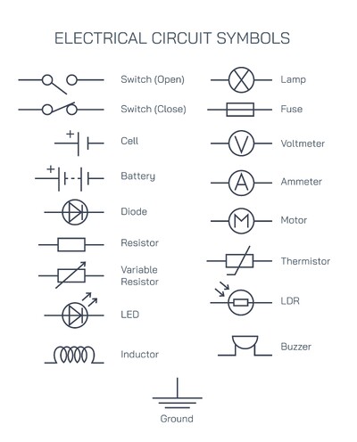
Ladder diagrams use standardized symbols to represent electrical components. Normally open contacts allow current to flow only when activated, while normally closed contacts allow current to flow until they are activated and opened. These contacts represent push buttons, limit switches, or relay contacts. Coils represent output devices such as relays or motor contactors. When a coil is energized, it changes the state of its associated contacts elsewhere in the diagram.
Other common elements include overload relays, timers, and auxiliary contacts. Together, these symbols create a logical flow that controls machines and processes safely and efficiently.
Motor Start-Stop Ladder Diagram Explanation
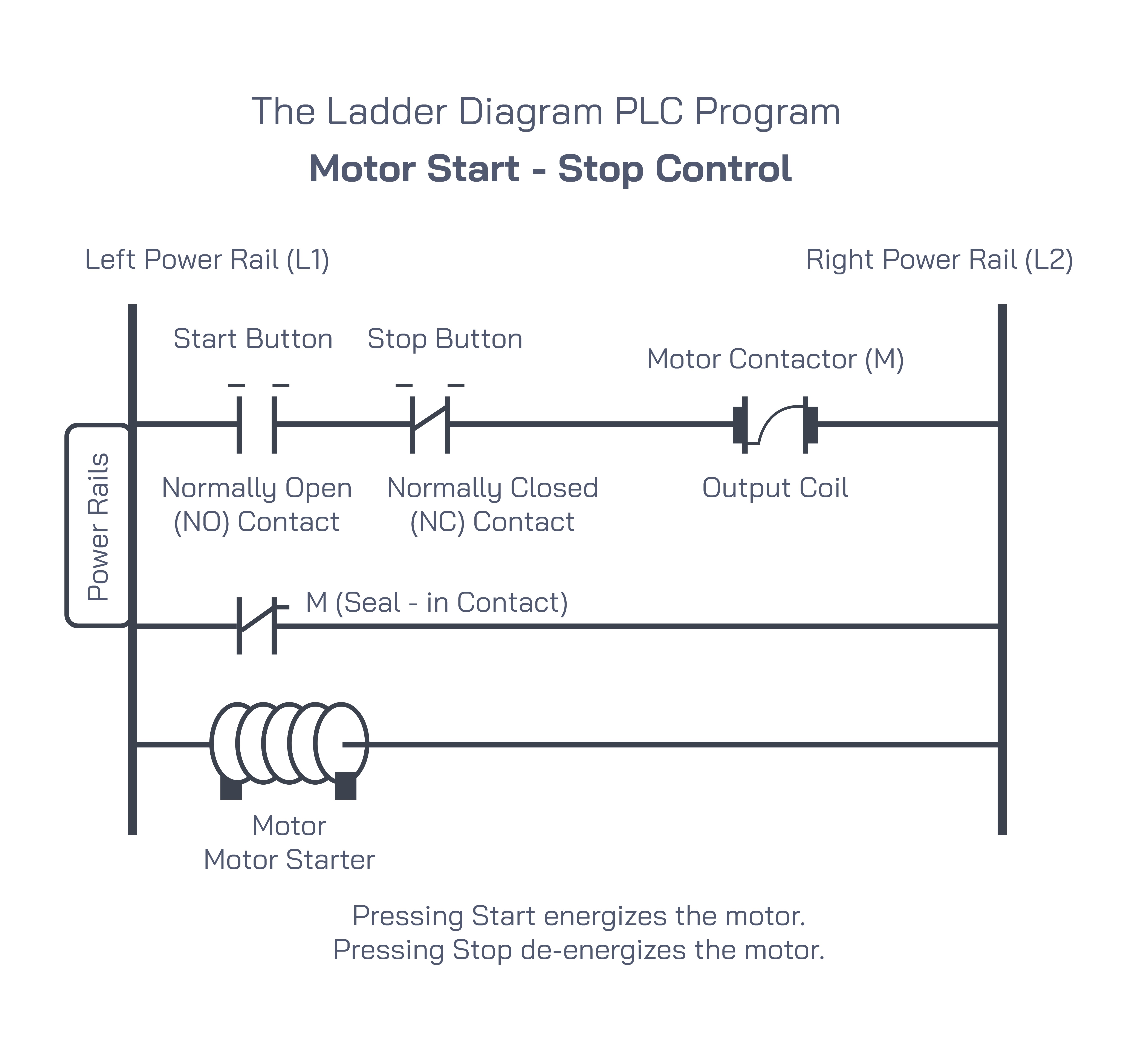
A classic example of a ladder diagram is the motor start-stop control circuit. In this circuit, a start button and a stop button are used to control the operation of an electric motor. The start button is normally open, meaning current flows only when it is pressed. The stop button is normally closed, meaning current flows through it under normal conditions and stops flowing when it is pressed.
When the start button is pressed, current flows through the normally closed stop button and energizes the motor contactor coil. This coil closes the main contacts that supply power to the motor, causing it to start running. At the same time, an auxiliary contact associated with the contactor closes and forms a seal-in circuit. This seal-in contact maintains current flow even after the start button is released.
When the stop button is pressed, the circuit opens, de-energizing the contactor coil. This causes the motor contacts to open and the motor to stop. This simple ladder diagram demonstrates fundamental control logic used in countless industrial applications.
Working Principle of Ladder Diagrams
The working principle of a ladder diagram is based on logical conditions. Each rung operates independently and is evaluated continuously. If all conditions on a rung are met, the output device is activated. If any condition becomes false, the output is deactivated. This behavior closely resembles the operation of physical relay circuits, making ladder diagrams highly reliable and predictable.
Ladder diagrams follow a scan cycle in automated systems, where inputs are read, logic is evaluated, and outputs are updated. This cycle repeats rapidly, ensuring real-time control of machines and processes.
Importance in Industrial Automation
Ladder diagrams play a vital role in industrial automation because they provide a clear and standardized way to design and troubleshoot control systems. They are widely used in manufacturing plants, power stations, water treatment facilities, and process industries. Electricians and technicians can easily interpret ladder diagrams to install, maintain, and repair control systems.
In programmable logic controllers, ladder logic programming is based directly on ladder diagram concepts. This allows industries to transition from relay-based systems to digital control without losing familiarity. Ladder diagrams also improve safety by ensuring predictable responses to input conditions.
Educational Significance
In technical education, ladder diagrams are a foundational topic. They help students understand the relationship between electrical components and logical control. By studying ladder diagrams, learners develop problem-solving skills and gain practical knowledge applicable to real-world electrical systems. Visual representation enhances comprehension and builds confidence in handling control circuits.
Advantages of Ladder Diagrams
Ladder diagrams offer several advantages. They are easy to read and understand, even for beginners. Their structure closely matches physical wiring, making troubleshooting straightforward. Ladder diagrams are flexible and can be expanded to include complex logic such as interlocks, timers, and safety circuits. Their standardized format ensures consistency across industries and regions.
Limitations and Modern Use
While ladder diagrams are excellent for discrete control systems, very complex processes may require additional programming methods. However, ladder diagrams remain relevant and widely used due to their clarity and reliability. Modern control systems often combine ladder logic with other programming techniques to achieve advanced functionality.
Conclusion
The ladder diagram is a fundamental tool in electrical control and industrial automation. Its ladder-like structure, standardized symbols, and logical flow make it an effective way to represent and control electrical systems. From simple motor start-stop circuits to complex industrial processes, ladder diagrams provide clarity, safety, and reliability. Understanding ladder diagrams is essential for anyone involved in electrical engineering, automation, or industrial maintenance, as they form the backbone of modern control systems.