Ammeter and Voltmeter Symbols — Electrical Measurement Circuit Diagrams
Understanding the Role of Meters in Electrical Measurement
In electrical science and circuit engineering, ammeters and voltmeters serve as two of the most fundamental instruments used to measure the behavior of electrical systems. An ammeter measures electric current flowing through a circuit, while a voltmeter measures the electric potential difference between two points. These devices allow engineers, technicians, and students to understand how electricity behaves under various conditions, ensuring circuits function safely and efficiently. Although physical meters vary widely—from analog needle-based instruments to digital multimeters—the principles behind their operation remain largely unchanged. A vector illustration of their symbols helps convey how these instruments are integrated into circuit diagrams, making electrical schematics readable and universally understood. These symbols provide clarity in designing, analyzing, and troubleshooting circuits, allowing anyone familiar with standard electrical notation to interpret how measurements are taken and how different circuit elements interact.
Symbol Structure and Representation of the Ammeter in Circuit Diagrams
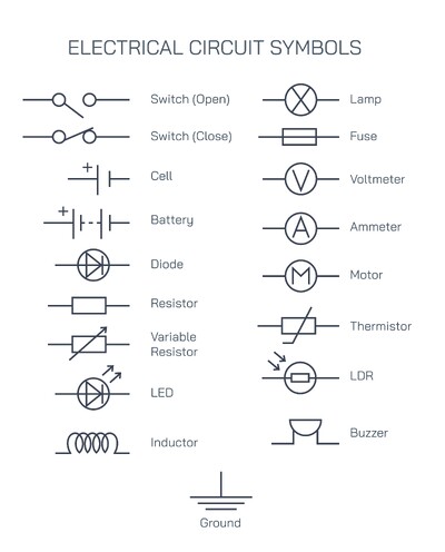
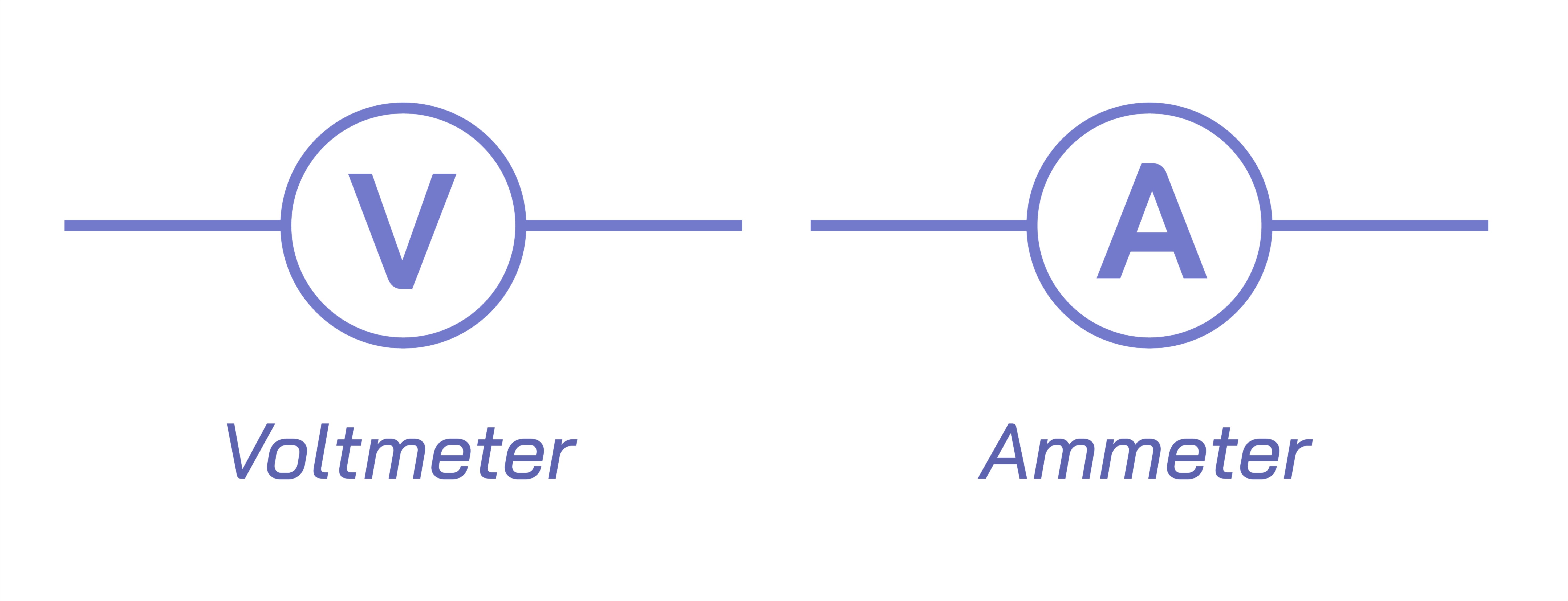
The ammeter symbol is typically represented by a simple circle containing the letter “A,” indicating its function as a current-measuring device. The circle connects directly in series with the circuit element or path where current measurement is required. This series placement is essential because current is identical at all points in a single continuous path, making it possible to measure the true magnitude of flow through a particular branch. The internal resistance of an ammeter is designed to be extremely low so that it does not introduce significant voltage drop or alter the behavior of the circuit being measured. In vector illustrations, the ammeter symbol reinforces this series connection visually by showing the meter in line with the conductor. Technical diagrams may also depict analog-style ammeters or digital interface versions, but the standardized circle-with-A symbol remains the universal representation. This simplistic yet highly functional design ensures that circuit diagrams across textbooks, engineering drawings, and electronic schematics communicate the same meaning regardless of context.
Symbolic Representation and Placement of the Voltmeter in Electrical Circuits
The voltmeter symbol mirrors the simplicity of the ammeter symbol by using a circle with the letter “V” at its center. However, unlike the ammeter, the voltmeter is always connected in parallel across the component or section of the circuit where voltage is being measured. This parallel connection allows the meter to detect the electric potential difference between two points without drawing significant current. To ensure this, a voltmeter is designed with extremely high internal resistance, preventing it from diverting current away from the component under test. A vector illustration of a voltmeter symbol often emphasizes this parallel layout by placing the symbol across two branches, demonstrating clearly that voltage is measured between points rather than through the path. This graphical clarity is important in academic settings, circuit design, and electrical diagnostics, where correct placement of a voltmeter ensures accurate and meaningful readings.
Differences in Function and Connection Principles Between the Two Meters
A deeper understanding of ammeters and voltmeters requires examining how their operational needs dictate their placement. Current, being the flow of electric charge, can only be measured by inserting an instrument into the path of that flow; thus, ammeters must always be in series. If placed incorrectly across a power source, they can cause a short circuit due to their low resistance. Conversely, the voltmeter—designed to measure potential difference—must never be placed in series. Doing so would provide meaningless readings while raising the circuit’s resistance dramatically. These contrasting requirements arise from the internal designs of the instruments: ammeters minimize their resistance to avoid affecting current, while voltmeters maximize resistance to avoid affecting voltage and current distribution. Understanding these principles is essential for anyone working with electronics, whether analyzing basic school-level circuits or complex industrial control systems.
Applications of Ammeters and Voltmeters in Practical Electrical Engineering
In practical electrical systems, ammeters and voltmeters appear in multiple forms, from panel meters installed in industrial equipment to handheld multimeters used by technicians. An ammeter can help diagnose issues such as excessive current draw, faulty components, or short circuits within wiring systems. A voltmeter can determine whether a power supply is functioning correctly, whether components receive the proper voltage, or whether resistive losses are occurring in long cables. Engineers rely on these instruments to validate circuit designs, monitor power consumption, and ensure electrical equipment operates within safe parameters. Modern digital meters often integrate both ammeter and voltmeter functionalities into a single multimeter, yet the underlying electrical symbols remain unchanged. These symbols are central to schematics for generators, motors, power distribution panels, household wiring diagrams, and electronic devices, ensuring universal communication in technical documentation.
Educational and Analytical Importance of Circuit Symbols for Meters
Circuit diagrams use symbolic representation because they abstract complex physical devices into clean, internationally recognizable icons. In educational contexts, these symbols introduce learners to the foundational ideas of measurement, electrical behavior, and circuit interpretation. They help students visualize experimental setups, understand how electricity flows, and practice analyzing circuits without needing to focus on the physical appearance of instruments. In advanced engineering contexts, symbols help standardize blueprints, allowing teams to collaborate on large-scale electrical systems without ambiguity. The ammeter and voltmeter symbols, being among the simplest yet most powerful, exemplify the elegance of symbolic electrical notation.
Illustrating Ammeter and Voltmeter Symbols in Vector Graphics
A vector illustration showing ammeter and voltmeter symbols would typically include two circles, one with “A” and one with “V,” each placed within stylized circuit segments. Arrows may indicate current direction through the ammeter, while the voltmeter may be shown connected across two points, visually reinforcing the parallel configuration. Additional diagrams may depict current flow lines, battery icons, resistors, or switch symbols to demonstrate how these meters integrate into broader circuits. Such illustrations help users understand not only the symbols themselves but also the practical context of how and why they are connected in particular ways.