Carnot Engine Diagram Showing Heat Reservoirs, Working Substance, and Thermodynamic Cycle
A Carnot engine represents the most idealized heat engine imaginable in thermodynamics, serving not as a machine that exists in practice but as a standard of perfection against which all real engines are compared. When illustrated in a vector diagram, the Carnot engine is typically displayed as a rectangular cycle or a circular loop connecting two thermal reservoirs — a high-temperature reservoir and a low-temperature reservoir — with a working substance in between that undergoes predictable and reversible transformations. Although the drawing itself is simple, it encodes one of the deepest scientific concepts in energy science: the limits of how efficiently heat can be converted into usable work. The ideal Carnot engine moves cyclically, drawing thermal energy from the hot reservoir, converting part of it into mechanical work, and releasing the remaining energy into the cold reservoir. Nothing about the cycle is accidental; every stage, every temperature difference, every heat exchange takes place under conditions that eliminate friction, turbulence, conduction losses, and any form of irreversibility. It is a conceptual machine that demonstrates how nature sets inviolable boundaries on energy conversion, regardless of technology or design.
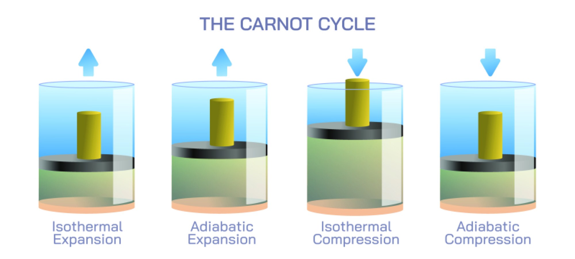
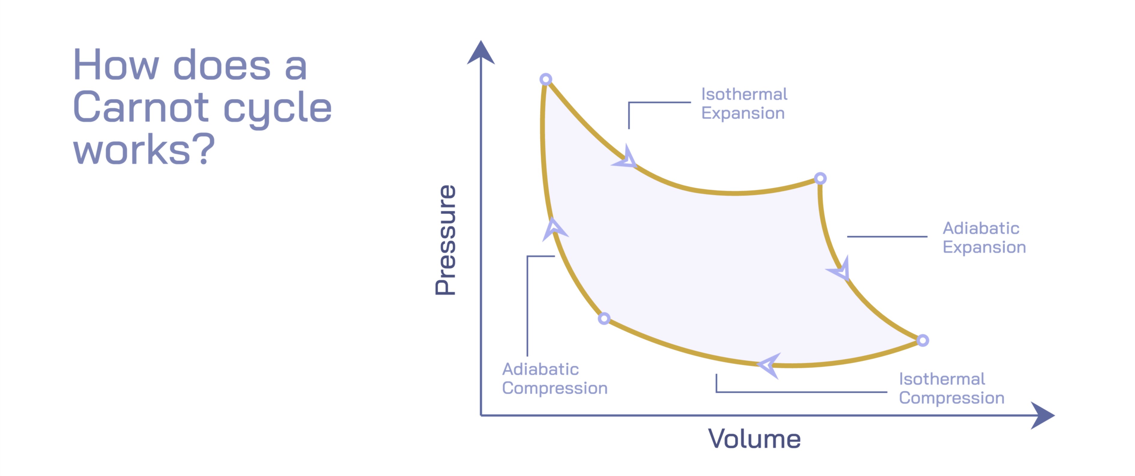
At the heart of the Carnot engine sits the working substance, which may be represented in the diagram as a closure around a gas in a cylinder connected to a piston. It does not matter whether the substance is steam, air, helium, or any ideal gas — the important feature is that it undergoes thermodynamic changes in a perfectly reversible sequence. During the cycle the working substance repeatedly expands and compresses, sometimes doing work on the environment and sometimes having work done upon it. For visual clarity, diagrams normally link the working substance to four distinct process stages in a closed loop that returns to its initial state after every rotation of the cycle. This return to the same starting point ensures that the internal energy of the system remains unchanged from one cycle to the next, meaning the only net outcome is that heat absorbed from the high-temperature reservoir has been partially converted into work with the rest discharged to the cold reservoir.
The high-temperature reservoir, positioned at the upper part of the illustration, represents a source of heat at a constant temperature. This reservoir does not cool down when supplying thermal energy, because theoretically it has infinite heat capacity. The working substance absorbs heat from this source during a high-temperature isothermal expansion, a phase in which the gas expands while maintaining constant temperature because heat continuously flows in from the reservoir to compensate for the energy the gas uses to push outward. In the diagram this stage is often marked by an arrow moving outward from the hot reservoir toward the working substance, symbolizing the transfer of energy. During this expansion the engine performs mechanical work — for example, pushing a piston outward — and the heat input at this stage, labeled in scientific demonstrations as
𝑄
𝐻
Q
H
, represents the primary driving energy of the cycle. Although the diagram is compact, this phase embodies a profound thermodynamic truth: meaningful work can only be produced when energy flows from a warmer region to a cooler region.
After this isothermal expansion the working substance undergoes an adiabatic expansion, meaning it continues to expand without transferring heat to or from the surroundings. In a Carnot cycle this shift is essential because it reduces the temperature of the working substance from that of the high-temperature reservoir to that of the cold reservoir entirely through internal energy redistribution. The diagram often indicates this stage as a transition from the upper reservoir temperature to the lower reservoir temperature, with no heat exchange marked along the path. The expansion still allows work to be produced, but the internal thermal energy decreases because no heat enters the system to replenish it. This connection between temperature, pressure, and volume highlights the intrinsic link between motion and microscopic energy in gases. When the working substance reaches the lower temperature boundary, it is positioned to interact with the low-temperature reservoir.
The low-temperature reservoir, commonly placed at the bottom of the vector illustration, acts as a heat sink that absorbs the waste heat that could not be converted into mechanical work. In the Carnot cycle, this interaction begins with an isothermal compression phase in which the working substance is compressed while releasing heat to the cold reservoir. The illustration usually depicts an inward-pointing arrow from the working substance to the cold reservoir to show that thermal energy leaves the system. Although compression requires work to be done on the working substance, the heat discharge to the cold reservoir enables the gas to maintain constant temperature during this phase. This portion of the cycle is labeled
𝑄
𝐶
Q
C
in thermodynamics, and it represents the unavoidable fraction of heat that cannot be transformed into useful work. Even in a perfect engine there will always be energy that must be expelled in order for the cycle to continue, demonstrating how no heat engine can ever achieve 100 percent efficiency.
Following this isothermal compression the cycle continues with an adiabatic compression, in which the temperature of the working substance rises from that of the low-temperature reservoir back to the high-temperature reservoir. No heat enters or leaves during this step; instead, the internal energy rises purely because of the work done on the gas. The diagram usually shows this final stage leading back to the starting point of the cycle, restoring the system to its initial thermodynamic state. By completing the closed loop the Carnot cycle forms a periodic system that converts heat input into mechanical output with no internal energy gain or loss per complete cycle. This closure emphasizes that the engine does not consume its working substance; instead, it uses the expansion and contraction of that substance as the medium to channel heat into motion.
What makes the Carnot diagram truly profound is not only the representation of the cycle stages themselves but the implication they carry about limits of efficiency. The Carnot engine is the most efficient heat engine possible for given temperature boundaries, and its efficiency depends solely on the temperatures of the hot and cold reservoirs. The greater the temperature difference, the greater the potential efficiency; the closer the temperatures become, the smaller the yield of usable work. In other words, the diagram broadcasts the message that improving practical engine efficiency does not rely only on machinery refinement but on the thermodynamic gap between input and output temperatures. No material, fuel, or engineering breakthrough can surpass the natural limit defined by that temperature ratio. This perspective is a turning point in science, reframing energy problems not as mechanical challenges but as fundamental constraints imposed by the laws of physics.
The circulating arrows that join the reservoirs and the working substance in the illustration also carry conceptual meaning. They reinforce the principle that heat engines produce work by allowing energy to flow from high temperature to low temperature. Without both reservoirs the process would stop entirely — a heat source without a sink cannot drive motion, and a sink without a source provides no energy to convert. The direction of arrows in the diagram, typically moving clockwise for a work-producing cycle, reflects the natural direction of thermodynamic processes. If the arrows are reversed, the same loop becomes a refrigerator or heat pump rather than a heat engine, highlighting the universality of the Carnot framework. Whether the device is producing work or transferring heat for cooling, the relationships among heat reservoirs, working substance, and reversible transformations remain the conceptual center.
A viewer examining a Carnot engine illustration sees a simple geometric cycle, but behind this simplicity lies the most important insight of thermodynamics: energy conversion has boundaries that no engine can violate. The Carnot cycle does not promise perfection in real engines; instead, it defines what perfection means in an absolute theoretical sense and gives scientists a tool to measure how close real engines, turbines, power plants, and refrigerators come to that ideal. Every piston system, steam turbine, internal combustion engine, jet engine, geothermal power plant, and industrial refrigeration unit stands in the shadow of the Carnot diagram — not in competition with it, but in recognition that the natural world determines the maximum work that heat can perform.
Thus, the vector illustration of the Carnot engine does more than label a hot reservoir, cold reservoir, and working substance. It visualizes the architecture of an ideal thermodynamic process in which energy, temperature, and work interact in perfect balance. It represents how the universe allocates heat between order and disorder, how motion arises from temperature differences, and why no machine can break the fundamental link between heat and entropy. The diagram is both a gateway to understanding mechanical efficiency and a philosophical reminder that even the most advanced technology must operate within the boundaries of physics. Through the elegant simplicity of the Carnot cycle, the brain learns not only how engines work, but how the world itself regulates the flow of energy.