Isotropic vs Anisotropic Materials — Comparison of Uniform Properties and Direction-Dependent Behavior in Material Science
Isotropic and anisotropic materials form one of the most important conceptual divisions in material science, because the way a material behaves under force, heat, light, electricity, or mechanical stress depends not only on its composition but on the uniformity or directionality of its internal structure. When students view a comparison illustration of isotropic and anisotropic materials, they are really learning how atomic arrangement determines real-world performance — why some materials respond the same regardless of direction while others behave differently depending on how stress or energy is applied. This comparison forms the foundation for understanding strength, deformation, conductivity, elasticity, and engineering choices across industries such as aerospace, automotive, civil construction, electronics, sports equipment and medical devices, where directional response to load or temperature determines reliability.
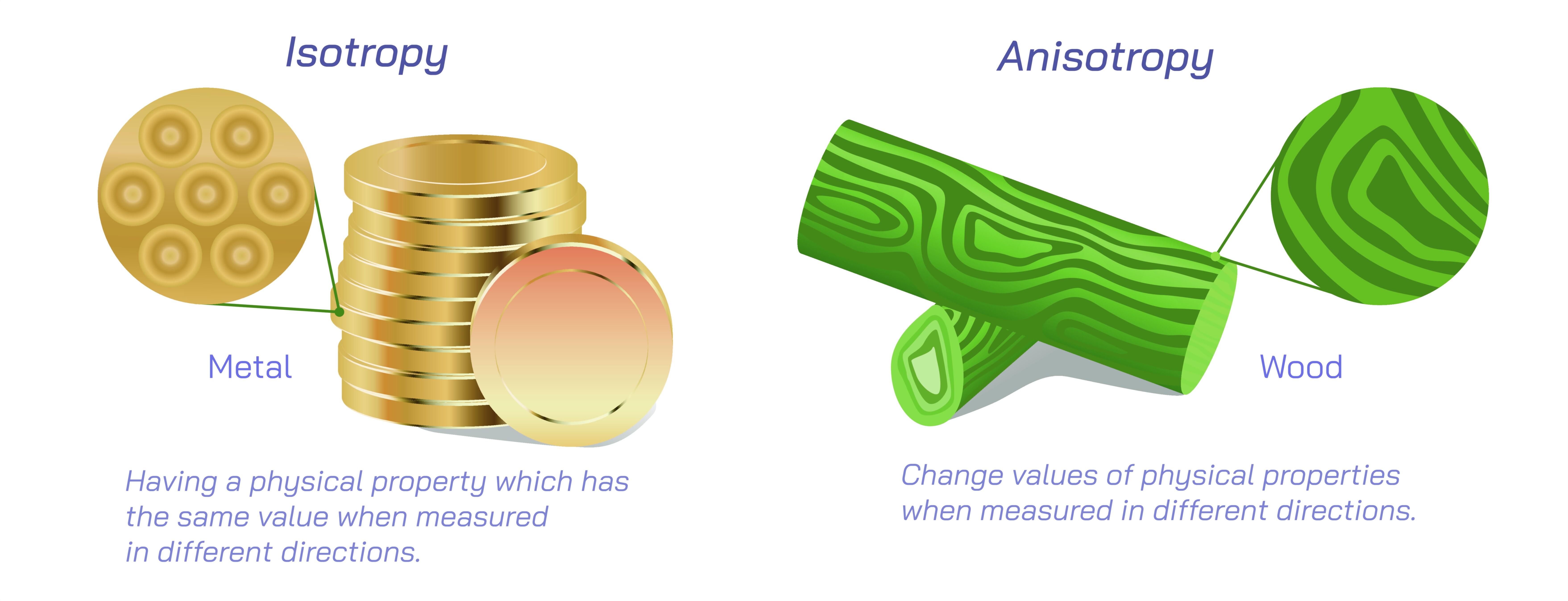
Isotropic materials are defined by uniform properties in every direction. Their internal structure is consistent and symmetrical, and their molecular or crystal arrangement does not create favored directions for stress or energy. A block of isotropic material behaves identically whether force is applied vertically, horizontally, or diagonally because the microscopic bonds and atomic distribution repeat symmetrically in all directions. In educational diagrams, this is represented visually by identical arrows extending outward from the center, equal-spaced lattice patterns, or circular symmetry grids showing that mechanical resistance, thermal conductivity, or optical behavior does not vary with orientation. Materials such as glass, rubber, many metals in fully annealed form, and fluids like water behave as isotropic media. When an isotropic object is stretched, compressed, bent or heated, the same response pattern occurs everywhere, allowing engineers to predict performance with simpler calculations. This uniformity reduces uncertainty and helps explain why isotropic materials are dependable for parts that receive multidirectional loads or are expected to behave consistently regardless of placement.
Anisotropic materials, in contrast, display properties that vary depending on direction. Their internal architecture is not symmetrical, and the bonding pattern, grain orientation, or molecular alignment creates axes along which the material behaves differently. In scientific illustrations anisotropy is depicted through directional arrows of varying length, elongated lattices, or fiber-like alignments representing regions of high or low stiffness, strength or conductivity. Wood is the best everyday example: it is far stronger along the grain than across it. Crystalline solids, composite fibers, carbon fiber, plywood, natural muscles, and single crystals all show anisotropic behavior. When force is applied in a direction aligned with strong internal bonds, the material may withstand very high loads, but when the same force is applied perpendicularly, the material may deform or break easily. Anisotropy enables high strength-to-weight performance when the direction of stress is known, which is why aerospace parts, bicycles, golf shafts, aircraft wings, and racing helmets often rely on carbon fiber laminates — strength is concentrated in deliberate directions, rather than wasted equally in every axis.
The reason isotropic and anisotropic properties differ lies in the internal arrangement of atoms and molecules. In isotropic materials, bonding occurs evenly across all directions — either because the atomic structure is highly disordered, as in amorphous solids, or because the crystalline structure repeats symmetrically enough that orientation does not matter. In anisotropic materials, structural patterns develop through repeated molecular alignment, preferred grain growth, or composite layering. This directional characteristic becomes a controlling factor in practical engineering. A turbine blade made from a single-crystal superalloy is intentionally anisotropic so that deformation and creep resistance are highest along the direction of rotation and thermal load. A baseball bat or violin bow takes advantage of wood’s anisotropy to combine rigidity and flexibility where needed. These examples help students see that anisotropy is not a flaw — it is a feature that must be understood, predicted and used wisely.
The distinction also applies to non-mechanical properties. Optical anisotropy explains why calcite splits light into two beams and why liquid crystal displays (LCDs) manipulate polarized light to form images. Electrical anisotropy in graphite allows charge to flow more easily along carbon planes than perpendicular to them. Thermal anisotropy in composite panels allows heat to be channeled sideways for efficient cooling. These effects broaden student understanding of anisotropy beyond simple breakage strength and demonstrate that material directional behavior governs an enormous range of technological innovations, from fiber-optic communication to advanced microchips. Illustrations comparing isotropic and anisotropic heat-flow or current-flow patterns reinforce how direction matters across physics, not just mechanics.
Engineers and designers use this knowledge to match material behavior with real-world demand. Where uniform performance is needed — such as machine housings, hydraulic components, bridges, or automotive wheel hubs — isotropic metals and alloys dominate. Where directional strength or tailored performance is preferable, such as in prosthetics, sports gear, drones, rockets, high-speed vehicles and orthopedic implants, anisotropic composite structures become the solution. The deeper students learn about these materials, the more they recognize that the right material is not simply the strongest one — it is the one whose directional behavior matches the intended load path and environmental working conditions.
Vector illustrations comparing isotropic and anisotropic materials make this concept intuitive through visual storytelling. A perfectly symmetrical grid symbolizes uniformity, while an elongated or layered structure conveys direction-dependent properties. Equal arrows represent identical strength in every axis, while directional arrows of different lengths show where a material is strong and where it is weak. A student or engineer who internalizes this visual comparison begins to recognize anisotropy intuitively when handling wood, bending a carbon-fiber strip, or observing layered crystals. They start predicting behavior rather than reacting to failure.
Ultimately, the comparison between isotropic and anisotropic materials teaches that matter is not defined only by its chemical formula but by the orientation of its structure. Two compounds with the same composition can behave drastically differently depending on atomic or molecular arrangement. This perspective allows learners to appreciate the relationship between internal order and external performance, and it reinforces the idea that nature and technology both rely on structure to achieve specific functions. Whether viewed in a classroom poster, a mechanical engineering chart, or a materials-science vector graphic, isotropy and anisotropy together reveal that the world of materials is rich not because everything behaves the same, but because different structural patterns give rise to specialized abilities that shape the objects, vehicles, machines and technologies that define modern life.