Reinforcement Column Arrangement — Structural Rebar Layout
Reinforcement column arrangement, often referred to as the structural rebar layout for columns, is one of the most critical components in reinforced concrete design because columns serve as the primary vertical load‐bearing elements in almost every structure. Whether in a multi-storey building, a bridge pier, an industrial framework, or a residential home, columns are the members through which loads from slabs, beams, and walls travel downward into foundations. The integrity of these columns therefore dictates the safety, stability, and durability of the entire structure. A carefully developed reinforcement layout ensures that the forces acting on a column—compression, bending, shear, buckling, and lateral forces—are properly resisted throughout the structure’s life cycle. Designing such an arrangement goes far beyond merely placing steel bars within concrete; it involves understanding load paths, material behavior, construction constraints, seismic demands, long-term durability, and code-based provisions that ensure safety across decades of service.
At the heart of reinforcement column arrangement is the configuration of longitudinal bars, which run vertically along the entire height of the column. These bars serve as the backbone that resists tensile stresses, particularly because concrete excels in compression but performs poorly under tension. In a perfectly axial scenario, columns might seem to require only compressive strength; however, real-world conditions rarely allow purely axial loads. Eccentricities from beams, uneven load distribution, wind, earthquakes, and structural deformation introduce bending moments that place portions of the column into tension. Longitudinal rebars absorb this tension and ensure that the column can deform safely without brittle cracking. The number, size, and distribution of these bars depend on the magnitude of loads but must always be arranged symmetrically to maintain balanced performance. Even distribution prevents the formation of weak sides, avoids twisting tendencies, and ensures uniform confinement by transverse reinforcement. In tall buildings, where columns must remain slender yet strong, the choice and positioning of longitudinal bars become even more critical, preventing buckling and enabling ductile behavior.
Transverse reinforcement, typically in the form of ties or spirals, wraps around the longitudinal bars and performs several indispensable roles. First, it confines the concrete core, increasing its strength and ductility. Without proper confinement, concrete subjected to high compression tends to crack and expand outward, causing premature failure. Second, ties prevent the longitudinal bars from buckling, especially under large compressive forces or cyclic loading from earthquakes. When columns sway during lateral movements, longitudinal bars may attempt to move outwards or bend; close transverse reinforcement holds them in place. Third, ties maintain the position of vertical bars during construction, ensuring that concrete covers remain intact and that bars do not drift too close to the surface where corrosion could compromise the structural capacity. The spacing, shape, and anchorage of ties depend on column dimensions, expected loads, and seismic design categories. In earthquake-prone regions, ties become more closely spaced near column ends, forming a confinement zone that enhances ductile behavior during strong shaking. These detailing requirements ensure that columns behave predictably, forming plastic hinges only in designated areas without collapsing suddenly.
The importance of clear cover—the distance between reinforcement and the outer concrete surface—cannot be overstated in the arrangement of column reinforcement. Clear cover protects reinforcement bars from moisture, chemicals, and environmental exposure that could cause corrosion. If the cover is too thin, steel becomes vulnerable, expanding as it rusts and cracking the surrounding concrete. If the cover is too thick, the bars lie too far from the most effective stress zones, reducing structural efficiency. Achieving optimal clear cover requires precision during detailing and construction because improper placement significantly affects column durability. Furthermore, fire resistance also depends on adequate cover. Columns exposed to high temperatures must retain structural strength long enough to allow evacuation and firefighting efforts. The protective concrete layer insulates the steel, slowing its temperature rise and preventing rapid loss of load-carrying capacity. This makes the correct reinforcement layout a crucial factor not just for structural reliability but also for life safety.
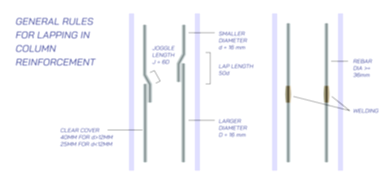
Column arrangement also involves decisions about lap splicing because reinforcement bars cannot always be extended seamlessly across multiple storeys. Lapping creates continuity between bars by overlapping them over a specified distance so that loads transfer effectively from one bar to the next. Incorrect lap placement is one of the leading causes of structural failure in columns. Ideally, laps are located at mid-height of the column, where bending moments are lowest. Lapping bars too close to the beam–column junction compromises the joint’s strength because these regions experience high shear and moment forces. Additionally, laps must be staggered rather than placed all in one plane to avoid creating a vertical line of weakness. Staggering ensures that only a fraction of bars are spliced at any given height, distributing stress transfer more evenly. In high-rise construction or seismic design, couplers are sometimes preferred to avoid long overlap lengths that create congestion. The splicing methodology is thus an integral part of the reinforcement arrangement and must be coordinated with structural demands, construction feasibility, and load behavior.
Reinforcement congestion is a significant practical concern when arranging columns, especially in areas where beams and slabs intersect the column. Beam bars, slab bars, and column bars must pass through or anchor around the joint without obstructing each other. If reinforcement becomes too congested, the concrete cannot flow through the gaps, leading to honeycombing, voids, or weak zones. Engineers therefore balance structural requirements with constructability, ensuring adequate spacing between bars and avoiding overly dense layouts. At times, smaller diameter bars may be chosen instead of fewer large bars, simply to improve constructibility and maintain clear spacing. In complex structural systems, especially seismic special moment-resisting frames, beam–column joints are highly loaded and require meticulous detailing to ensure that reinforcement from different directions does not clash. Column reinforcement arrangement therefore becomes a coordination effort among structural designers, draftspeople, and contractors.
The influence of structural load paths is central to determining the reinforcement layout of a column. Loads from beams, slabs, and walls converge into column heads. The reinforcement arrangement near these regions must accommodate the load transfer smoothly. Regions near beam–column joints typically require additional confinement reinforcement to handle concentrated stresses and shear forces. The column’s cross-sectional shape—whether rectangular, circular, square, or composite—also influences the reinforcement pattern. Rectangular columns typically use rebars along each face, ensuring bars in corners are properly tied due to high stress concentrations at these locations. Circular columns rely on spirals or continuous ties, creating uniform confinement that enhances ductility. Composite columns, which combine steel sections with concrete and reinforcement bars, present even more intricate detailing requirements because bars must interact with steel shapes, ensuring composite action without creating weak zones.
In seismic design, reinforcement arrangement becomes even more rigorous and controlled. Earthquakes subject columns to repeated and rapidly reversing lateral forces that create alternating regions of tension and compression. If columns are not detailed properly, brittle failure modes such as shear cracking or bar buckling can occur, leading to catastrophic collapse. To prevent this, seismic codes require closely spaced ties throughout the plastic hinge regions, ensuring strong confinement and preventing shear failure. Additionally, longitudinal bars require precise placement to ensure they can sustain large deformations without buckling. Columns in seismic frames are designed to remain stronger than beams, adhering to the “strong column–weak beam” philosophy so that inelastic deformation occurs in beams rather than columns. Achieving this balance relies heavily on the reinforcement layout within columns, making the detailing not just a technical requirement but a philosophical one that governs the survival of the structure during strong seismic events.
The durability of reinforced concrete columns is heavily influenced by reinforcement arrangement. Columns exposed to coastal environments, aggressive chemicals, industrial pollutants, or freeze–thaw cycles must be detailed with enhanced attention to protection. The reinforcement arrangement must allow adequate clear cover, minimize bar clustering, and ensure uniform concrete compaction. In structures where corrosion risk is high, epoxy-coated bars or alternative reinforcement materials may be selected, but layout principles remain similar. Ventilation of formwork, vibration practices, and concrete mix design interact directly with the reinforcement arrangement. Even the best-designed rebar layout can perform poorly if concrete cannot properly penetrate all gaps or if the bars shift during construction. This highlights that reinforcement layout is not separate from construction technique; it is deeply integrated with every step of execution.
Complex architectural designs often require nonstandard column shapes, such as L-shaped, T-shaped, octagonal, or oval columns. Reinforcement arrangement in such irregular geometries becomes more challenging because load paths are not uniform and corner stresses vary more dramatically. Engineers must place longitudinal bars at corners that experience the highest bending, with additional intermediate bars along faces to distribute stresses. Transverse reinforcement must be contoured to the shape of the column, ensuring proper confinement in every region. These layouts demand precise drafting and site execution, as mistakes in placing bars in nonrectangular sections can drastically reduce load-carrying ability.
Where columns carry very heavy loads—such as in industrial plants, transfer floors, or bridge piers—the reinforcement arrangement must include larger bars, denser ties, and sometimes bundled bars. Bundling bars increases capacity but must be arranged with great care so that concrete can flow between bundles. Additionally, the use of high-strength reinforcement requires modified detailing rules because high-strength bars behave differently under inelastic deformation. The arrangement must reflect these behavioral differences while maintaining compliance with structural codes.
Reinforcement arrangement also influences column behavior under accidental loads such as fire, blast, or impact. Closely spaced ties improve resistance to sudden loads by preventing bar buckling and maintaining cohesion between steel and concrete. In fire scenarios, reinforcement positioned correctly with adequate cover delays the heating of steel, retaining strength longer. In blast-resistant design, reinforcement must be arranged to accommodate rapid energy release, preventing fragmentation. These considerations demonstrate how the reinforcement layout is tied directly to structural resilience beyond normal load conditions.
Ultimately, reinforcement column arrangement represents the synthesis of structural understanding, practical construction needs, and long-term performance requirements. It determines how a column will carry and distribute loads, how it will resist earthquakes, how long it will endure in corrosive environments, and how reliably it will protect the safety of occupants and the integrity of the building. Each detail—from the placement of longitudinal bars to the spacing of ties, from lap splicing strategies to clear cover dimensions—contributes to a complex system that holds up the entire structure. The arrangement must therefore be executed with precision, guided by fundamental principles of engineering mechanics, adherence to building codes, and thoughtful consideration of construction realities. Through careful planning and execution, reinforcement column layouts ensure that columns remain strong, stable, and resilient, supporting the built environment safely and dependably for generations.
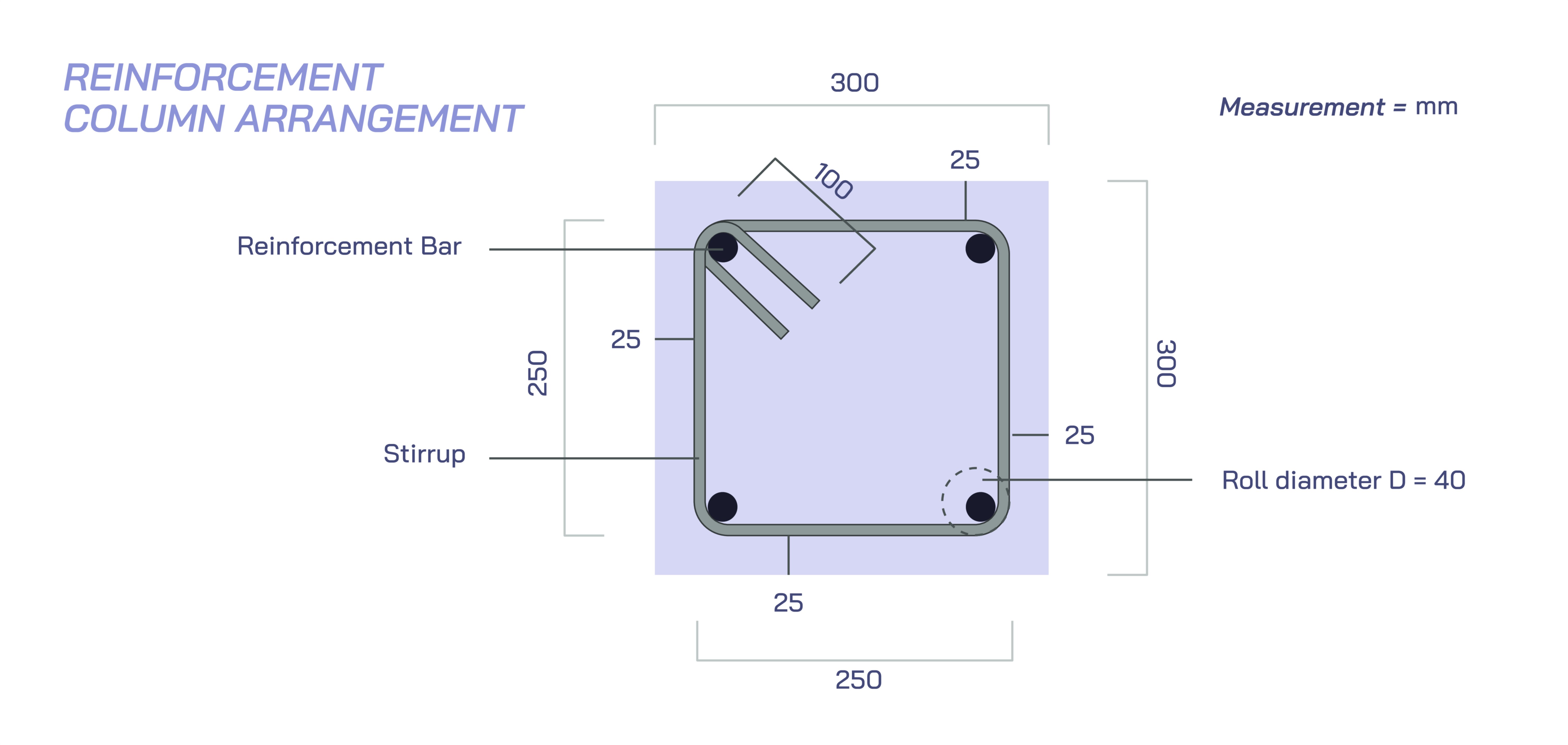
Reinforcement Column Arrangement — Structural Rebar Layout Vector Illustration
Reinforcement column arrangement vector illustration showing steel rebar placement, ties, and spacing details for civil engineering and construction education.
Summary
Related Images







File Details
File Type
-
EPS
File Size
-
5.83 MB
File Dimension
-
Scalable vector file
Your contribution helps us create more resources, but please support only if it's comfortable and affordable for you.❤️️