Direct Current and Alternating Current Showing Flow Types, Electrical Symbols, and Circuit Comparison
Direct current (DC) and alternating current (AC) represent the two fundamental ways in which electric charge travels through a conductive pathway, and a detailed comparison of their flow patterns, electrical symbols, and circuit behavior forms the foundation of understanding modern electrical and electronic systems. Although both types of current perform the essential role of moving electrons to deliver energy to devices, their internal behavior is strikingly different, and visual illustrations help reveal what the physics alone cannot convey at a glance. With DC, the flow of electric charge moves in one steady, unidirectional path—like water running continuously downstream in a river. With AC, the direction of current reverses rhythmically, shifting back and forth many times per second—more like ocean waves that move forward and backward in a repeating, periodic motion. These contrasting flow types determine not only how the two currents behave inside a wire but also how circuits are designed, how power is distributed, and what kind of electrical devices can operate from each supply.
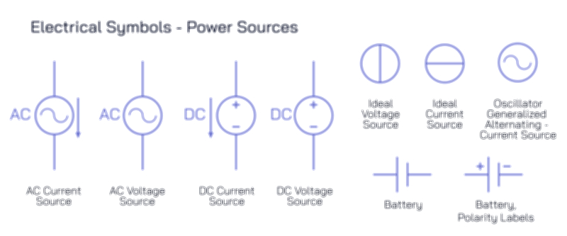
A basic illustration of DC depicts electrons traveling from the negative terminal of a source toward the positive terminal without changing direction. In practice, this type of current is generated by electrochemical reactions inside batteries, photovoltaic effects in solar panels, and the steady output of DC power supplies. Because the voltage remains constant rather than oscillating, DC is particularly well-suited for electronics that require consistent voltage levels, such as smartphones, computers, LED lighting systems, and microprocessors. On an electrical diagram, DC is represented by a straight line positioned above a dashed line, symbolizing a stable output. Circuit schematics featuring DC typically include a battery symbol—a sequence of alternating long and short parallel lines indicating positive and negative terminals. This format reminds the viewer that DC sources contain fixed polarity, and reversing the terminals in a circuit reverses the charge flow.
AC, in contrast, is depicted by a sinusoidal wave symbol because the current repeatedly changes direction in a smooth, periodic pattern. Power stations generate AC by rotating electromagnetic coils in magnetic fields, causing voltage to fluctuate rhythmically from positive to negative. As a result, the electrons inside a wire oscillate rather than travel continuously in a single direction. Although this oscillating motion might intuitively seem less efficient than steady DC flow, it brings crucial advantages over long distances. Because the voltage of AC can be transformed easily through step-up and step-down transformers, it is ideal for large-scale power distribution—transmitting electricity across cities and countries with minimal energy loss. AC circuit diagrams use the wave-like symbol to represent alternating potential, and household wall sockets provide AC because most appliances designed for motors, heating, and large power loads operate most efficiently from alternating voltage.
From a circuit design perspective, the differences between DC and AC determine how electrical components behave. A visual comparison of the two often shows a straight arrow for DC current flow versus a reversing arrow that oscillates in both directions for AC. In a DC circuit, the current flows steadily from the negative terminal, through conductors and loads, and back to the positive terminal, maintaining constant polarity at every moment. Polarity-sensitive components, such as diodes, LEDs, and capacitors, behave differently depending on the direction of DC flow, requiring proper orientation for safe and correct operation. In AC circuits, however, the polarity flips repeatedly, meaning that components designed for AC must be able to tolerate continual reversal. Devices like induction motors use this alternating reversal to generate rotation, while resistive appliances such as water heaters convert AC energy into heat with no concern for polarity.
A detailed educational illustration often places the symbols and flow diagrams of DC and AC side by side to show how the two types of current differ visually and conceptually. The DC diagram displays constant voltage and a fixed-direction electron path, while the AC diagram shows a sinusoidal waveform with rhythmic alternating polarity. Comparing circuits visually gives even deeper insight. DC circuits feature a smooth voltage distribution and are ideal for precision electronics, small portable devices, and digital circuitry where stable potential differences are required. AC circuits, by contrast, are built to handle higher power delivery across greater distances and are essential for residential and industrial electricity networks.
Beyond basic flow characteristics, AC and DC also differ in how they interact with circuit components, especially passive ones like capacitors and inductors. In a DC environment, a capacitor eventually charges and blocks further DC flow, while an inductor supports the flow with minimal opposition. In an AC system, the same capacitor continually charges and discharges with the alternating voltage, allowing current to pass dynamically, while an inductor resists changes in current because the oscillation constantly disrupts its magnetic field. Although these processes can be shown mathematically, a visual diagram comparing circuit behavior provides a much clearer understanding of how the physical characteristics of current influence the use of each component type in different engineering applications. This is one reason why AC dominates power distribution grids and large appliance motors, while DC dominates microelectronics, computing hardware, and low-voltage control systems.
A practical illustration comparing sources reinforces how each supply is generated and used. Batteries, solar cells, fuel cells, and USB-powered charging systems supply DC because they produce stable, unidirectional voltage through chemical or photoelectric means. Power plants, generators, and household electrical outlets supply AC because rotational mechanical energy converted into electrical energy naturally produces alternating polarity. The two systems interact constantly in modern life through power conversion equipment, such as AC-to-DC adapters used in phone chargers and DC-to-AC inverters used in solar power systems. A visualization showing power flowing from grid AC into adapters and then into DC-based devices helps confirm the idea that both types of current are essential in different aspects of everyday technology.
Safety and transmission considerations further highlight the contrasting identities of AC and DC. Because AC voltage can be transformed easily through coils and magnetic coupling, power companies distribute electricity at high voltage to reduce energy loss and then lower the voltage before it enters homes and workplaces. DC cannot be transformed as simply without electronic converters, which historically made long-distance DC distribution inefficient. However, modern high-voltage DC (HVDC) technology, used in large-scale power transmission systems worldwide, takes advantage of low-loss DC flow over extremely long distances, especially underwater and between national grids. This illustrates that AC and DC are not competitors but complementary solutions, each optimized for different tasks.
The final comparison in a detailed educational illustration often categorizes applications: DC for digital electronics, energy storage, microprocessors, sensors, and low-voltage control circuits; AC for home appliances, industrial motors, lighting systems, and power distribution grids. This pairing reinforces that neither current type is inherently better — rather, they are engineered for different roles based on their internal flow characteristics. DC offers precision and stability, while AC offers efficiency and scalability.
In its complete educational role, a visual representation of direct current and alternating current with flow types, electrical symbols, and circuit comparison becomes far more than a chart of differences. It provides clarity on how electrons behave in different environments, shows why certain forms of current power certain technologies, and helps new learners appreciate the unseen yet essential motion of electrical energy that runs everything from smartphones to factory machinery. By presenting DC and AC together in one illustration—each with its own flow logic, symbology, and circuit architecture—the viewer gains a unified understanding of how the world of electricity works at every level, from tiny microchips to national power grids.