Electrical Symbols — Circuit Components and Diagram Representation
Electrical symbols form the visual language of circuit representation, offering a structured way to depict the countless components, connections, and functional relationships that exist within electrical systems. These symbols transform complex circuits into clear, standardized diagrams that engineers, technicians, and students can interpret with precision. Although each symbol is small and simple on its own, together they create detailed maps of electrical behaviour, showing how current flows, how components interact, and how energy is managed within a system. Understanding this symbolic language involves more than memorizing shapes; it requires appreciating how each symbol reflects the physical nature, purpose, and behaviour of the component it represents. By exploring the meaning behind these symbols and the logic that brings them together, the entire process of reading and creating circuit diagrams becomes a deeper and more intuitive experience.
At the heart of circuit diagrams lies the principle of simplification. Real electrical components vary in size, shape, material, and configuration, but diagrams reduce them to minimalistic representations that highlight their essential functions. A resistor in physical form may be a tiny cylindrical body with coloured bands, but in a diagram it appears as a simple jagged line or a rectangular block. A capacitor, physically composed of layered plates or rolled foil, becomes two parallel lines or a combination of a straight line and a curved one. These symbols do not attempt to mimic appearance; they capture purpose. Each line, bend, or shape is an abstraction chosen to reflect what the component does in a circuit — whether it stores energy, resists flow, controls direction, switches currents, converts energy, or measures parameters. The clarity of this symbolic language ensures that someone studying a circuit diagram can understand its function even without seeing the actual components.
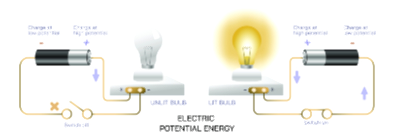
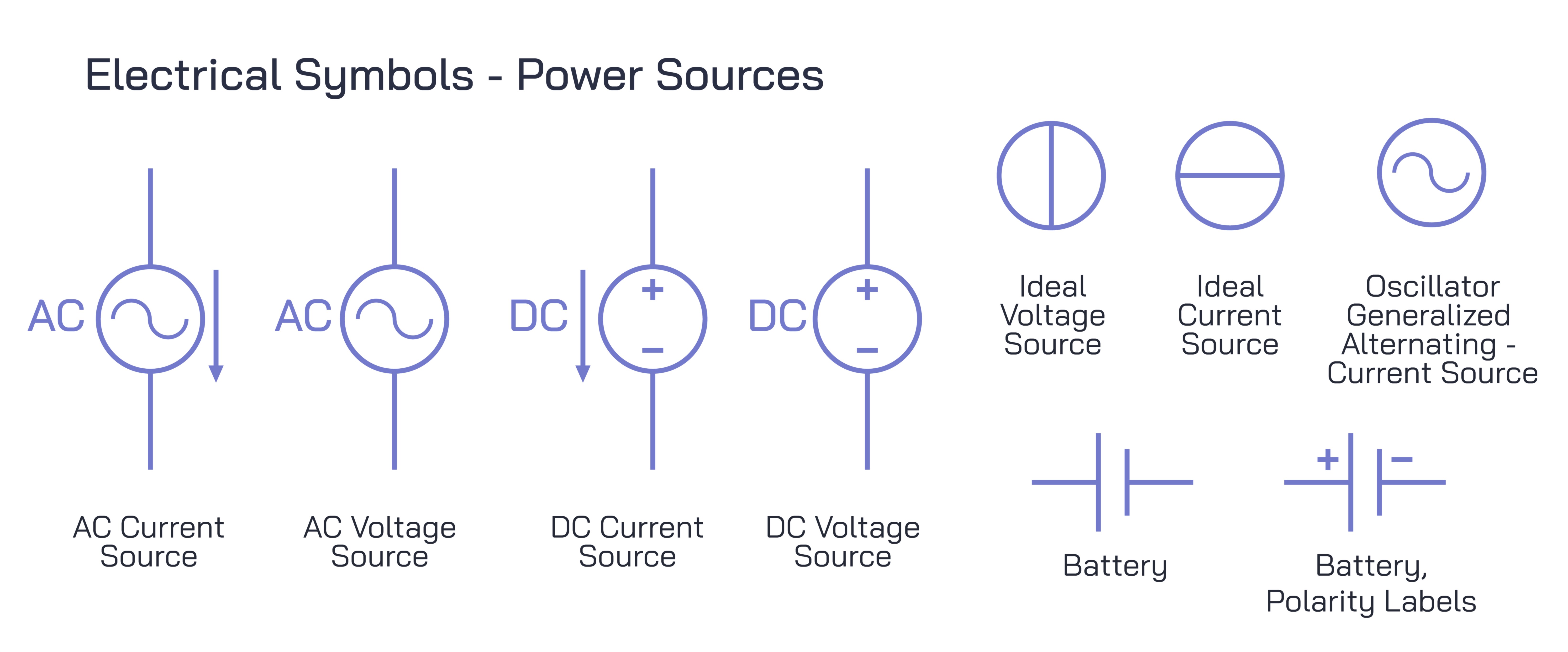
One of the most foundational symbols in circuit diagrams is the battery symbol. It typically appears as a pair of lines — one longer, one shorter — representing the positive and negative terminals. This symbol condenses the complex chemistry and engineering of a battery into a simple visual reminder: one end provides higher electric potential, and the other provides lower potential. The battery symbol sets the tone for the flow of current across the diagram, indicating source direction and establishing the divisions between power supply and load elements. It becomes the anchor of many schematic representations, guiding how the rest of the circuit is understood.
Resistors, which limit current and divide voltages, often appear as zigzag lines or as rectangles depending on regional conventions. Their symbol emphasizes their role in opposing the motion of charges. Variable resistors expand this concept by adding arrows or sliding contacts to indicate adjustability. These variations reflect how resistors can be fine-tuned during calibration or used to vary brightness, speed, or volume in electronic systems. Understanding the symbolic differences between fixed and variable resistors allows a reader to instantly interpret whether a particular part of the circuit is designed for static control or live adjustment.
Capacitor symbols show two separated plates, symbolizing their ability to store electric energy in an electric field. A polarized capacitor adds curved or differently styled lines to indicate orientation, reminding the designer that such components must be placed correctly in the circuit. Inductors, represented by loops or coils, symbolize magnetic energy storage and the winding of wire around a core. These symbols uncover the dual nature of energy storage in circuits — capacitors storing energy electrically, inductors storing it magnetically — and reveal how these components influence oscillations, filtering, and timing functions.
Switches add an entirely different dimension to circuit diagrams through their representations of mechanical control. A simple open switch appears as a break in a line with a tilted connector, while a closed switch shows a continuous connection. More complex switches such as push-buttons, toggle switches, and selector switches incorporate variations that show whether they return automatically to a default position or remain locked in place. These symbolic distinctions allow readers to imagine the behaviour of a circuit over time, predicting when power is delivered or interrupted based on the switch configuration.
Semiconductor components introduce a new level of symbolic complexity. Diodes, transistors, and integrated circuits rely heavily on symbolic notation to show direction, control, amplification, and logic-processing functions. A diode symbol includes an arrowlike triangle pointing toward a line, expressing the idea of one-way current flow. Light-emitting diodes include rays or arrows that indicate light output. Transistor symbols incorporate multiple connecting lines, arrows, and shapes to reveal how current flows between terminals and how one current controls another. Although these symbols may appear intricate, they bring clarity to the inner workings of modern electronics. Without such visual cues, understanding how signals are amplified, switched, or modulated would be significantly more difficult.
Meters and measurement devices also rely on standardized symbols. A voltmeter may appear as a circle with the letter “V,” while an ammeter uses the letter “A.” These symbols are simple yet effective, revealing where measurement tools are connected within a circuit diagram. They help engineers understand how diagnostic readings were taken and where monitoring points exist within a system. Even though measurement devices influence circuits in subtle ways, their symbols allow clear interpretation of testing conditions and instrument placement.
Connections and grounding symbols are equally crucial because they define how components relate within the circuit environment. Dots indicate nodes where connections join, while crossing lines without dots indicate paths that do not interact. Ground symbols, often depicted as horizontal lines narrowing downward or triangular forms pointing downward, mark reference points that maintain stability in the circuit. These grounding symbols signify electrical zero levels, safety pathways, and return routes for current. Without clearly defined grounding, circuits would behave unpredictably, and diagrams would lose their clarity.
Integrated circuits, microcontrollers, and logic gates each employ more abstract symbols to express complex functions in simplified form. A rectangle representing an integrated circuit may contain pins labeled for input and output. Logic gates, used in digital circuits, appear as distinctive shapes — curved for OR gates, flat and angled for AND gates, or triangular with bubbles for NOT gates. These symbols represent operations that manipulate binary information, reflecting how modern digital technology processes data. The simplicity of these symbols belies the internal complexity of the components they represent, turning dense electronic architecture into readable, functional logic diagrams.
Wiring layouts within circuit diagrams also follow symbolic conventions. Straight lines represent conductive paths, but the way they are arranged communicates structure. Parallel connections signify branching circuits, while series arrangements indicate sequential pathways. Diagrams label certain lines as buses, representing groups of signals traveling together. This organization ensures that circuit diagrams remain clear even when depicting large, complex systems.
In specialised fields such as power systems or communications, additional symbols expand the vocabulary. Transformers use paired coil symbols to show how energy is transferred between circuits through magnetic coupling. Antennas are depicted with branching lines that suggest radiation or reception of electromagnetic disturbances. Motors and generators have stylized symbols that express their rotational or energy conversion behaviour. Each symbol encapsulates a complete device and its role in the broader system.
When all these symbols are combined within a single diagram, the result becomes an intricate map of interactions. A complete schematic reveals where energy originates, how it is manipulated, how signals are shaped, and how loads respond. The careful arrangement of symbols conveys sequence, hierarchy, and function. Someone trained in reading these diagrams can trace the flow of energy and information through the circuit without ever touching the actual components. They can identify potential faults, optimize performance, or modify behaviour through interpretation of symbols alone.
Beyond technical utility, electrical symbols highlight the cultural and collaborative nature of engineering. The standardization of symbols across countries and industries ensures that diagrams created in one part of the world can be understood by engineers far away. This shared symbolic language fosters innovation, communication, and collaboration across borders. It allows teams to develop new technologies, troubleshoot systems, and share knowledge with ease. Even in education, students learning electronics begin by mastering these symbols, gaining access to the vast world of electrical engineering through this visual lexicon.
Understanding electrical symbols also empowers non-experts to interpret diagrams found in household devices, automotive manuals, or appliance repair guides. Recognizing the symbol for a fuse, for example, helps someone locate protective components. Identifying a switch or relay symbol allows basic troubleshooting. Even without deep knowledge of circuit theory, the ability to read symbols offers practical benefits, helping people understand how energy flows through the systems they use every day.
Ultimately, electrical symbols embody the balance between simplicity and complexity that defines engineering. Each symbol acts as a compact representation of a physical component, yet when combined, they reveal the full richness of circuit design. This symbolic system turns invisible electrical processes into visible, understandable diagrams that capture the essence of technology. Through this language, engineers and learners alike gain the ability to visualize, analyze, and craft the electrical systems that power modern life — from household electronics to communication networks, industrial machines, and advanced digital technologies.