Core type and shell type transformers are two fundamental constructional forms of transformers used extensively in electrical power systems. While both types perform the same essential function of transferring electrical energy between circuits using electromagnetic induction, they differ significantly in physical structure, magnetic flux distribution, winding arrangement, and practical applications. Understanding these two transformer constructions is crucial for students, engineers, and professionals working in electrical and power engineering, as transformer design directly influences efficiency, performance, cooling, insulation, and cost.
A transformer, regardless of its type, operates on the principle of electromagnetic induction. When an alternating current flows through the primary winding, it produces a time-varying magnetic flux in the core. This magnetic flux links the secondary winding and induces an alternating voltage in it. The transformer thus transfers electrical energy from the primary circuit to the secondary circuit without any direct electrical connection. Core type and shell type transformers differ mainly in how the windings and magnetic core are arranged to facilitate this energy transfer.
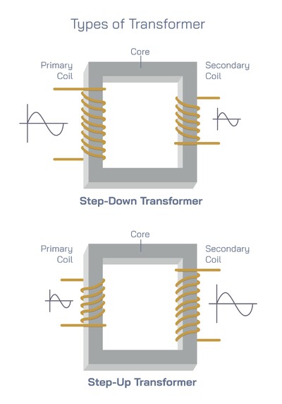
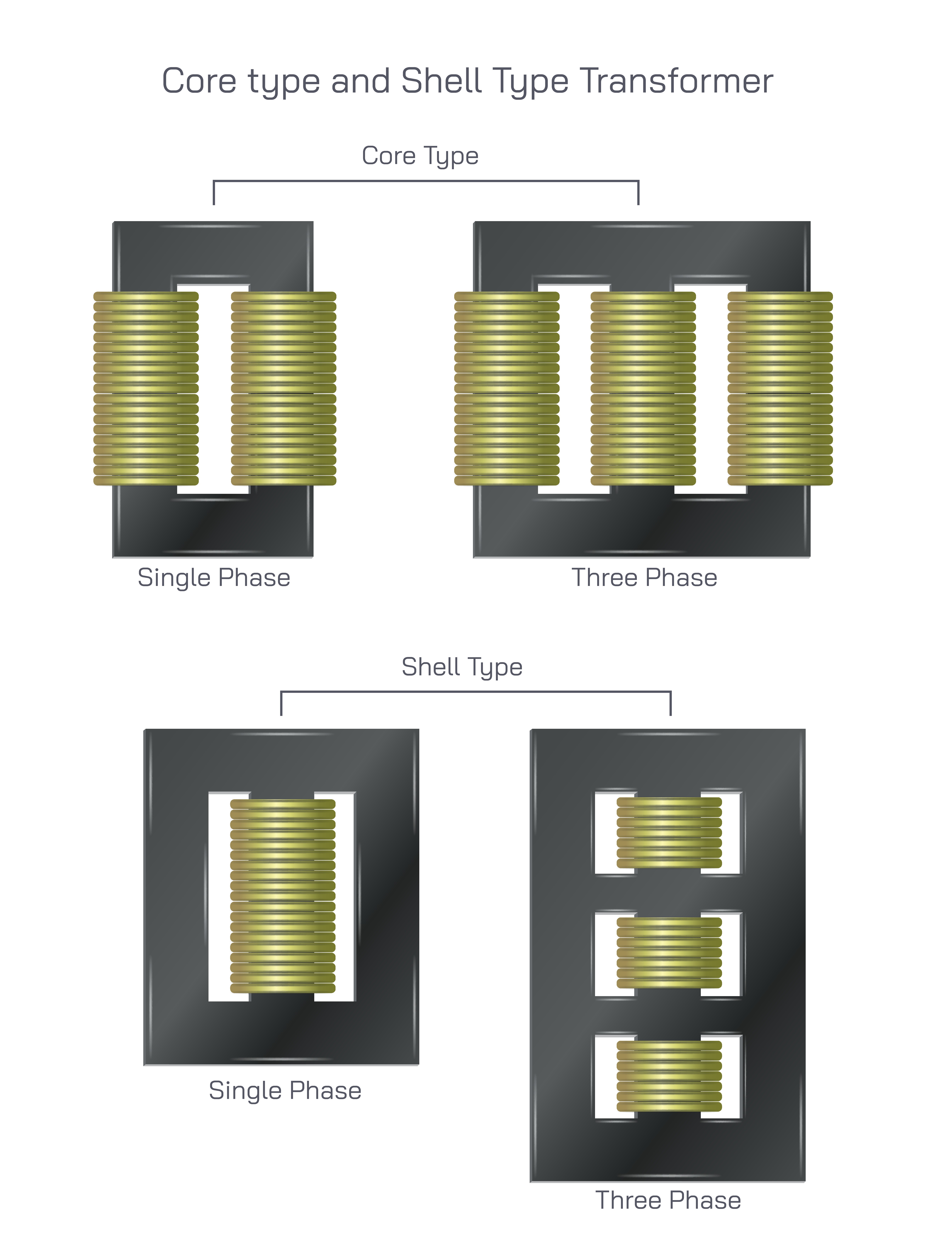
In a core type transformer, the windings are placed on two opposite limbs of a laminated magnetic core. The core is usually rectangular or square in shape and is constructed from thin sheets of silicon steel laminated together to reduce eddy current losses. In this design, both the primary and secondary windings are wound concentrically on the same limb or divided equally between the two limbs. The core essentially surrounds a portion of the windings, which is why it is referred to as a core type construction.
The magnetic flux in a core type transformer follows a single continuous path through the core. When alternating current flows in the primary winding, magnetic flux is established in the core, passes through the limbs and yoke, and completes the magnetic circuit. Because the windings are placed on the limbs and are relatively exposed, core type transformers generally have better cooling characteristics. Natural air circulation around the windings allows heat to dissipate efficiently, making this type suitable for applications where cooling is a critical factor.
Core type transformers are commonly used in high-voltage applications. The arrangement of windings allows for easier insulation between the high-voltage winding and the core, which is essential when dealing with elevated voltage levels. The mechanical structure of core type transformers is relatively simple, and the windings are more accessible for inspection and maintenance. These characteristics make core type transformers popular in power transmission systems and substations where high voltage handling and reliability are paramount.
In contrast, a shell type transformer has a distinctly different construction. In this design, the magnetic core surrounds the windings almost entirely. The windings are placed on the central limb of a three-limb or multi-limb core structure. The core is built in such a way that it forms a shell around the windings, hence the name shell type transformer. The primary and secondary windings are usually wound one over the other on the central limb, which provides excellent magnetic coupling.
The magnetic flux path in a shell type transformer is divided into multiple parallel paths. The flux generated in the central limb splits into two equal parts and flows through the outer limbs of the core before completing the magnetic circuit. This division of flux reduces magnetic leakage and improves overall efficiency. Because the windings are enclosed by the core, shell type transformers offer superior mechanical protection to the windings and better resistance to short-circuit forces.
Shell type transformers are particularly well suited for low-voltage, high-current applications. The compact arrangement of windings and core results in shorter mean length of turns, which reduces copper losses. Additionally, the close proximity of primary and secondary windings improves electromagnetic coupling, further enhancing performance. Due to these advantages, shell type transformers are widely used in distribution networks, electronic circuits, and industrial power systems.
Cooling characteristics differ between the two types. In shell type transformers, the windings are enclosed by the core, which can restrict natural air flow. As a result, these transformers often rely on additional cooling methods such as oil immersion or forced cooling systems. However, the robust mechanical design provides excellent protection against external damage and vibration, making shell type transformers suitable for environments with mechanical stress.
When comparing core type and shell type transformers, several key differences become evident. Core type transformers have windings that surround the core, while shell type transformers have a core that surrounds the windings. In core type designs, magnetic flux follows a single path, whereas in shell type designs, the flux divides into multiple paths. Core type transformers generally require more copper due to longer winding lengths, while shell type transformers use more core material because of their multi-limb structure.
The choice between core type and shell type construction depends largely on the application. For high-voltage power transmission and large power ratings, core type transformers are often preferred due to easier insulation and effective cooling. For low-voltage, high-current applications where efficiency and mechanical strength are critical, shell type transformers are typically selected. Both designs are used in single-phase and three-phase configurations, as shown in the diagram, demonstrating their versatility in different electrical systems.
In single-phase core type transformers, two windings are placed on two limbs of the core, whereas in three-phase core type transformers, three sets of windings are distributed across three limbs. Similarly, shell type transformers can be designed for single-phase operation with windings on a central limb or for three-phase operation with windings arranged on multiple central limbs within a shared core structure. These variations allow engineers to tailor transformer designs to specific voltage levels, power capacities, and installation requirements.
From an efficiency perspective, both core type and shell type transformers can achieve high performance when properly designed. Losses such as copper loss and core loss are minimized through careful selection of materials and optimized geometry. Laminated silicon steel cores reduce hysteresis and eddy current losses, while high-quality copper or aluminum windings ensure efficient current flow.
In conclusion, core type and shell type transformers represent two essential approaches to transformer construction, each with distinct structural and operational characteristics. Core type transformers emphasize ease of insulation, effective cooling, and suitability for high-voltage applications, while shell type transformers focus on compact design, strong magnetic coupling, and mechanical robustness. Both types play a vital role in electrical power systems, enabling efficient voltage transformation and reliable energy transfer across a wide range of applications. Understanding their differences and advantages provides valuable insight into transformer technology and the broader field of electrical engineering.