Welding Symbols — Complete Guide to Welding Diagrams and Meanings
Understanding the Purpose and Importance of Welding Symbols
Welding symbols serve as a universal graphic language that communicates detailed welding instructions directly on engineering drawings, blueprints, and fabrication sheets. These symbols eliminate ambiguity by providing a precise, standardized method for conveying how a weld should be performed, what type of joint is required, which side of a component must be welded, and what finishing processes must be applied. Instead of relying on long written explanations or verbal clarifications, welding symbols encapsulate complex directions into a single visual format that is universally recognized by engineers, welders, inspectors, and fabricators. This system is grounded in standards such as AWS (American Welding Society) and ISO, ensuring that welders across different industries can read and interpret the symbols consistently. Welding symbols thus bridge the gap between design concepts and practical execution, ensuring that every weld contributes accurately to the structural integrity, safety, and performance of the final product.
The Structure of a Welding Symbol: Arrow, Reference Line, and Tail
A welding symbol is not a single mark but a multi-part graphic that conveys different types of information through its arrangement. At the core is the reference line, the primary horizontal guideline on which specific weld indicators are placed. Connected to it is the arrow, which points to the exact location on the drawing where the weld must be applied. The arrow may refer to the “arrow side” or “other side” of the joint, and this positional distinction determines which side receives the weld. The tail, which may or may not be present, is used to specify supplementary information such as welding processes, electrode types, or special instructions. Above and below the reference line appear symbols representing weld types, dimensions, contours, lengths, and finishing requirements. By organizing instructions around these structural components, welding symbols convert a complex multi-step welding requirement into a clear visual sequence that welders can follow with confidence and precision.
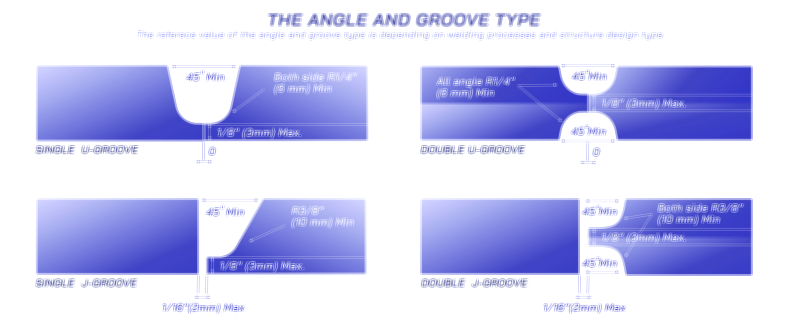
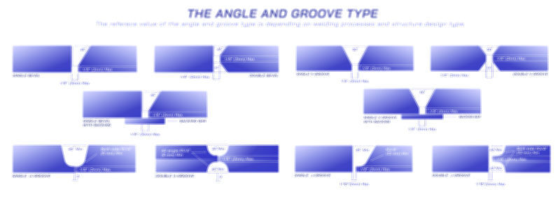
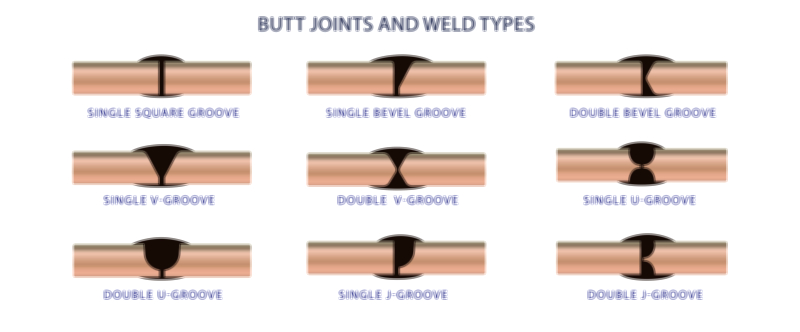
Common Weld Types Represented in Welding Symbols
Welding diagrams incorporate a wide range of weld types, each symbolized through specific shapes or graphic representations. Fillet welds, among the most common, use a triangular symbol to indicate the triangular cross-section of the joint produced when two surfaces meet at right angles. Groove welds—which include square, V-groove, U-groove, J-groove, and bevel grooves—are represented through distinct shapes that reveal how the material edge must be prepared. For example, a V-shaped groove symbol indicates that both edges are beveled to create a V-shaped channel requiring full or partial penetration. Plug and slot welds are shown as circular or elongated shapes, indicating where metal must be filled to secure overlapping plates. Surfacing welds use a rectangular bar to show where metal should be deposited for buildup or wear resistance. Spot and seam welds, typically associated with resistance welding, are represented by circular and straight line symbols. Each of these symbols conveys the fundamental geometry of the weld, ensuring that fabricators understand exactly what kind of joint preparation and welding technique is required.
Dimensions, Orientation, and Supplementary Details in Welding Symbols
Welding symbols also communicate exact measurements and orientations, ensuring welders produce joints that meet structural and mechanical specifications. Dimensions such as weld size, length, pitch, and spacing are placed on specific sides of the symbol according to strict conventions. For example, the size of a fillet weld is indicated to the left of the symbol, while the length of the weld appears to the right. If intermittent welds are required, the symbol includes values for both segment lengths and center-to-center spacing. Contour symbols—such as convex, concave, or flat—appear above or below the weld symbol to specify the desired finished shape, often accompanied by finishing instructions such as grinding, machining, or hammer peening. Weld all-around symbols appear as a small circle placed at the junction of the arrow and reference line, indicating that the weld must completely encircle the joint. Field weld symbols, designated by a small flag, communicate that the weld must be performed on-site rather than in the workshop. These supplementary details ensure that every aspect of the weld meets design expectations, from geometric accuracy to final appearance.
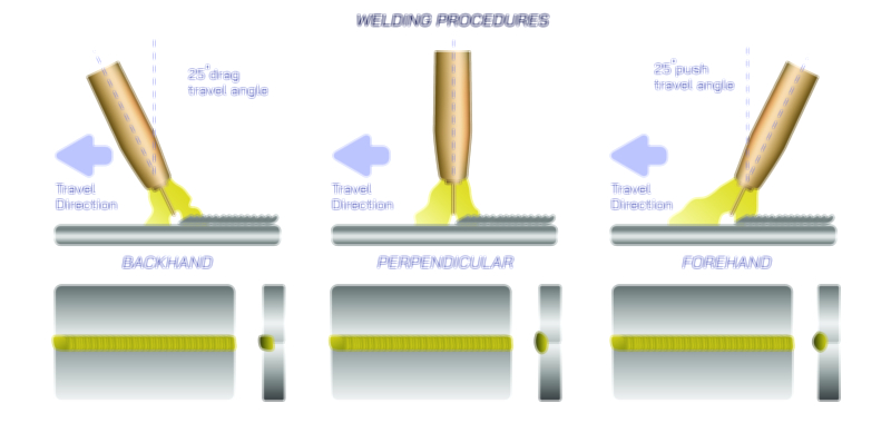
Interpreting Complex Weld Symbols in Engineering Drawings
While many welding symbols are straightforward, complex structures often require more intricate graphic combinations. Multiple welds may be indicated on the same reference line, stacked above or below one another to represent sequential operations or multi-pass welds. Combination groove and fillet welds appear on drawings where structural requirements demand enhanced strength or reinforcement. Staggered intermittent welds use offset symbols to demonstrate alternating weld placement for load distribution. In multi-reference diagrams, arrows may connect to multiple joints, each requiring distinct weld types. Understanding how to interpret these complex arrangements requires familiarity with standards and careful attention to symbol placement. For welders working on bridges, pipelines, pressure vessels, aircraft frames, or heavy machinery, these symbols ensure that structural welds meet strict regulatory requirements and safety codes. Proper interpretation of these diagrams minimizes errors, reduces rework, and guarantees that assembled components will perform as intended under demanding operational conditions.
Applications of Welding Symbols Across Industries
Welding symbols play a foundational role across industries that rely on precision metal joining. In construction and structural engineering, they guide the creation of safe frameworks for buildings, towers, and bridges. In the automotive and aerospace sectors, welding symbols ensure that chassis, frames, engine components, and aircraft structures are assembled to exact mechanical tolerances. Shipbuilding, pipeline construction, heavy equipment manufacturing, and energy industries all rely on consistent symbol interpretation to ensure that welds can withstand pressure, vibration, thermal fluctuations, and environmental exposure. Even artistic metalwork and industrial fabrication shops use welding diagrams to maintain consistency in custom or high-volume projects. Across all these fields, welding symbols function as a universal interpreter between engineering vision and physical craftsmanship, ensuring alignment between design and execution.
Illustrating Welding Symbols and Their Meanings
Vector illustrations depicting welding symbols typically show individual weld symbols alongside real-world joint diagrams, visually linking the geometric shapes of symbols to the actual form of welded connections. These illustrations often include reference lines, arrows, and tails that demonstrate how symbols are arranged in professional blueprints. Groove profiles are drawn cross-sectionally to show how metal edges must be shaped before welding, while fillet welds are depicted in three-dimensional views to illustrate bead geometry. Supplementary symbols—such as contour indicators, finishing marks, weld-all-around circles, and field-weld flags—are included as overlays to help users identify their placement and meaning. These visuals serve as essential teaching tools for welders, students, engineers, and inspectors, offering clarity that strengthens skill development and ensures accuracy during fabrication.