Siphon in Fluid Mechanics Vector Illustration Showing Liquid Flow Between Containers Using Pressure Difference
A siphon is a simple yet fundamental device in fluid mechanics that enables liquid to flow from one container to another, often at a lower level, without the need for pumps, relying instead on pressure differences and gravity. Siphoning is widely used in various applications, from transferring fuel or water to draining aquariums or cisterns. A vector illustration of a siphon typically depicts the U-shaped tube, the relative heights of the source and receiving containers, the direction of liquid flow, and the pressure differentials driving the motion. This visual representation helps explain the physical principles underlying siphoning, including atmospheric pressure, hydrostatic pressure, and gravitational forces. By clearly demonstrating the mechanics of fluid movement, the diagram provides an accessible and educational depiction of a phenomenon that might otherwise seem counterintuitive.
At the heart of the vector illustration is the U-shaped tube, which connects two containers. The tube must first be filled with liquid, either by immersion or priming, so that no air remains in the system. In diagrams, arrows indicate the flow direction from the higher liquid level (source container) to the lower liquid level (receiving container). The vector representation often includes color coding or shading to distinguish the liquid from the surrounding air, emphasizing the continuity of the fluid column. The height difference between the liquid surfaces in the two containers is a crucial factor, as it determines the hydrostatic pressure driving the siphon. The illustration may label the heights
ℎ
1
h
1
and
ℎ
2
h
2
for the source and receiving containers, respectively, showing that the liquid will flow as long as the outlet is lower than the surface of the source.
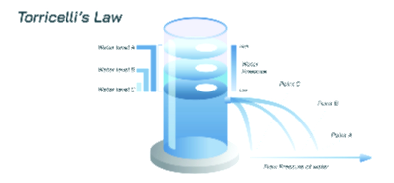
Pressure differences are central to the siphon mechanism and are often highlighted in vector diagrams. Atmospheric pressure acts on the liquid surfaces of both containers, while the liquid column within the tube experiences hydrostatic pressure proportional to its vertical height. The pressure at the apex of the tube, which is higher than both containers, is slightly lower than atmospheric pressure due to the weight of the liquid columns. The diagram may include labels or arrows indicating this pressure gradient, demonstrating that the combination of atmospheric pressure and gravitational potential allows liquid to be "pulled" over the tube’s crest and flow downward. This visual conveys the idea that the siphon does not violate gravity but rather harnesses the interplay between pressure and weight to maintain continuous flow.
Vector illustrations often depict the velocity of liquid within the siphon using arrows along the tube’s path. The liquid accelerates as it moves from the higher to the lower surface, with the flow rate dependent on the height difference, tube diameter, and frictional losses along the tube. Cross-sectional views may include annotations of Bernoulli’s principle, showing the relationship between pressure, velocity, and elevation at different points in the tube. For example, pressure is lowest at the tube’s apex where velocity is highest, while pressure increases as the liquid descends into the receiving container. By integrating these principles, the illustration provides a quantitative understanding of siphon dynamics beyond the simple directional flow.
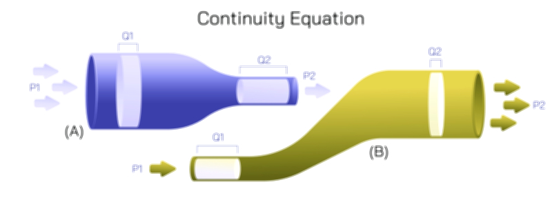
The continuity equation may also be represented in vector form. For an incompressible fluid, the flow rate
𝑄
=
𝐴
⋅
𝑣
Q=A⋅v remains constant along the tube, where
𝐴
A is the cross-sectional area and
𝑣
v is the velocity. Vector diagrams may include variable tube diameters with arrows of proportional length to indicate changes in velocity, demonstrating how narrowing or widening sections influence the speed of liquid. This inclusion emphasizes the mechanical and geometrical factors that affect siphon efficiency in practical applications.
Additional elements often included in vector illustrations are source and receiving container labels, showing initial and final liquid levels, and flow direction arrows, emphasizing the continuous motion over the apex. In some educational diagrams, dashed lines may represent the maximum tube height that can be sustained, illustrating the limit imposed by atmospheric pressure. If the tube’s apex exceeds approximately 10 meters for water at sea level, the siphon will fail, as atmospheric pressure is insufficient to maintain a continuous liquid column. This detail connects the illustration to real-world constraints and physical laws, providing a deeper understanding of limitations.
Vector illustrations may also show practical variations, such as siphoning with flexible tubing, siphons in fuel systems, or siphons used to drain rainwater from tanks. Labels and arrows can indicate gravity-assisted flow, priming methods, or pressure equalization points, helping learners understand both theory and application. Color gradients can distinguish potential energy levels, showing the reduction in gravitational potential as the fluid moves from the source to the receiver.
By combining tube geometry, container levels, liquid flow direction, pressure gradients, and velocity vectors, a siphon vector illustration provides a comprehensive depiction of the physics behind this seemingly simple phenomenon. The diagram helps viewers visualize how atmospheric pressure, hydrostatic pressure, and gravity work together to enable liquid transfer, illustrating both the conditions necessary for operation and the limitations imposed by physics.
Ultimately, the vector illustration conveys that a siphon is not merely a tube over which liquid flows but a dynamic system governed by fluid mechanics principles, including pressure differences, gravitational potential, continuity, and energy conservation. It bridges conceptual understanding and practical application, making the process of liquid transfer intuitive, scientifically grounded, and visually comprehensible. By integrating flow direction, pressure distribution, and height relationships into a single coherent image, the diagram serves as an effective educational tool for students, engineers, and anyone studying the fundamentals of fluid mechanics.