Types of Beams Used in Construction – Structural Design Principles, Load-Bearing Behavior, Material Variations, Support Conditions, and Engineering Significance in Modern Buildings and Infrastructure
Beams form the backbone of nearly every construction project because they are the primary structural members responsible for supporting loads and transferring forces safely to columns, walls, or foundations. Whether a building stands stable, a bridge spans across a valley, a roof holds its weight against weather, or an industrial platform carries heavy machinery, beams are working silently inside the framework to resist bending, shear, and deflection. A beam is more than just a horizontal element; it is a mathematical and physical solution to the problem of weight distribution. Engineering history shows that as architectural challenges grew, humans repeatedly developed new beam types to respond to longer spans, taller buildings, stronger vibrations, earthquake stresses, and dynamic moving loads. Today, construction uses a wide range of beam classifications based on material, support arrangement, structural cross-section, and design purpose. Understanding each type gives insight into why structures remain durable, safe, and resilient over decades or even centuries.
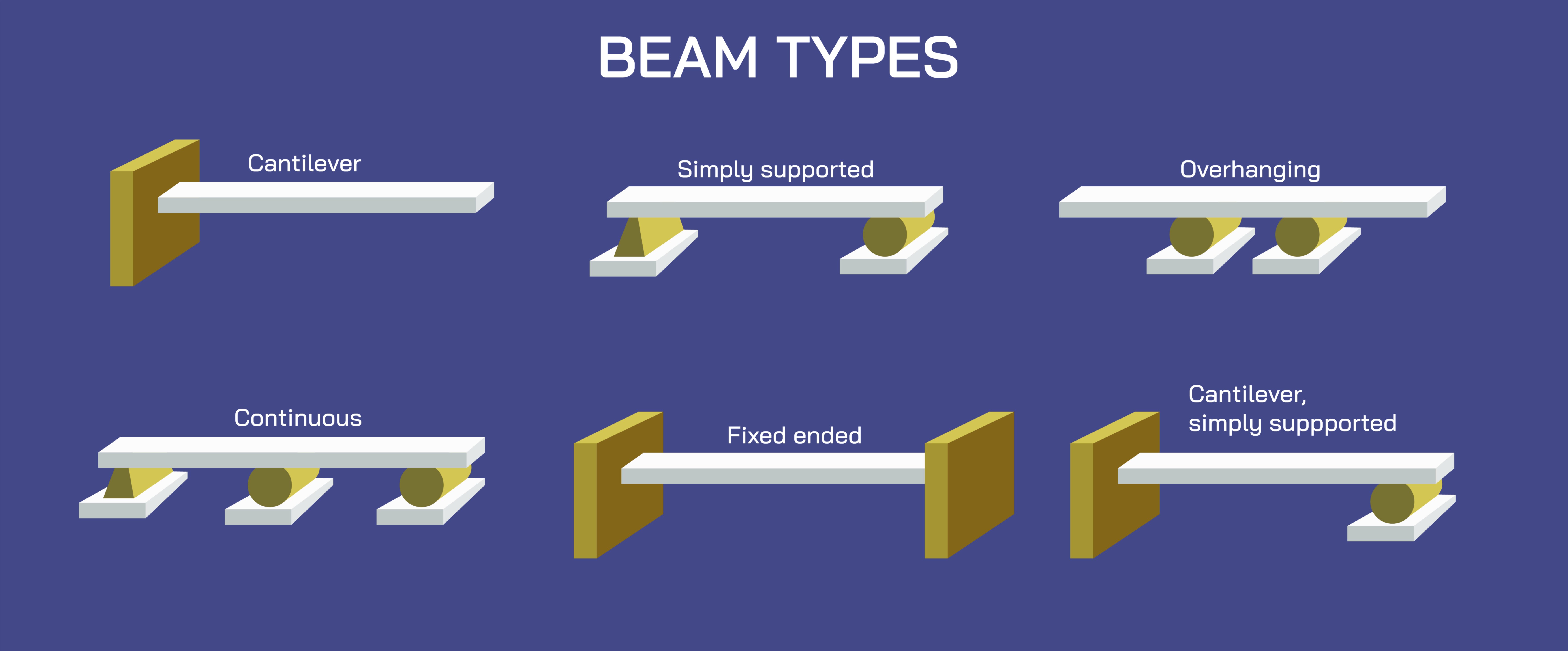
One helpful way to classify beams is based on how they are supported. The most fundamental of these is the simply supported beam, which rests freely on two supports—typically with a pin on one end and a roller on the other—allowing rotation without restricting the beam’s natural expansion due to temperature or loading. Simply supported beams are common in residential floor systems, small bridges, mezzanines, and warehouse roofing. Because they are unconstrained at the ends, they bend downward under load and create both compression on the top fibers and tension on the bottom fibers. Their predictable bending pattern makes them easier to analyze, and construction crews favor them because their installation is straightforward and adaptable to variable site conditions. However, because their load-resisting ability relies on the beam’s bending strength alone, they must be sized carefully to prevent excessive deflection and cracking.
More structurally constrained are fixed beams, supported rigidly at both ends such that rotation at the supports is restrained. This rigidity reduces the bending deflection in the middle of the beam, making fixed beams especially useful when stiffness must be maximized—for example, in industrial floors carrying heavy equipment, cantilevered concrete balcony slabs, or high-rise construction where even small deflections can disturb glass façades or internal finishes. The restrained support conditions reverse the bending pattern compared with simply supported beams, causing negative moments near the supports and positive moments at the center. This distribution allows designers to optimize reinforcement or steel profile placement precisely where stresses are highest. The fixed beam type demonstrates that the behavior of a beam is not solely dependent on its size or material, but on how it is connected into the structure.
A specialized structural configuration is the cantilever beam, supported at one end while free on the other. Cantilevers illustrate one of the most dramatic feats of engineering—the ability to project into space without secondary external support. In buildings, cantilevers appear as balconies, roof overhangs, projecting canopies, signage supports, and dramatic architectural projections that create floating forms. In bridges, cantilevered sections enable long spans over rivers or obstacles without placing temporary supports in the water. Because all the bending moment and shear are concentrated near the fixed support, cantilever beams require high material strength and careful reinforcement. Unlike simply supported beams, where the bottom is in tension, cantilevers produce tension on the top fibers near the wall and compression at the bottom due to reversed bending. The cantilever class reveals how creativity in structural design allows architecture to defy what appears to be visual gravity.
Another support-based classification is the continuous beam, which spans over more than two supports. Continuous beams are highly efficient because loads are shared across multiple spans rather than concentrated on a single section. This redistributes stresses and reduces the maximum bending moment in each segment, allowing designers to use slimmer sections over long distances. In highways, rail bridges, industrial buildings, and multi-story commercial frames, continuous beams ensure smooth load transfer where numerous columns line up across a structure. They also help control deflection better than individual single-span beams and improve seismic and vibrational performance by absorbing energy across several supports. Continuous beams demonstrate that structural behavior improves when components are interconnected rather than isolated.
Beams can also be classified based on the geometry of their cross-section, since the shape determines how efficiently the material handles tension, compression, and shear. The most common shape is the I-beam or H-beam, whose twin flanges separated by a vertical web maximize bending resistance with minimal weight. W-section beams are widely used in steel-framed buildings and bridges because they provide high load capacity for long spans. In contrast, a rectangular beam—commonly seen in reinforced concrete floors—has a uniform cross-section and relies on steel rebars to resist tension while concrete handles compression. Its solid mass makes it less efficient per unit weight compared to I-beam profiles, but concrete beams gain advantages in fire resistance, stiffness, and seamless architectural integration.
Where additional resistance to lateral forces and torsion is required, engineers use T-beams, L-beams, and channel beams. A T-beam combines a flange at the top with a web underneath and often appears when the slab and beam become a single composite member. It is highly effective when compression concentrates near the top of the beam. Channel beams, shaped like the letter C, provide partial flange support while allowing easy fastening on one side and appear in lightweight framing, rails, and bracing systems. Angle beams, shaped as an L-section, often serve as secondary beams and bracing members in trusses and industrial frames. The diversity of beam sections shows how precise geometry—rather than only mass—controls structural behavior.
Looking beyond basic shapes, certain beam categories emerge because architects and engineers must solve special challenges. Box beams or hollow box girders, constructed from steel plates or precast concrete, create stiff hollow rectangular sections that provide superior torsional resistance. They dominate in long-span bridges and flyovers where twisting forces from wind or traffic must be controlled. A related form, the truss beam, is a beam composed of interconnected triangular bracing using slender steel members. It achieves long spans with very little material by directing forces through axial tension and compression rather than bending. Truss beams appear in factories, aircraft hangars, stadium roofs, towers, and expanding bridges. Meanwhile, plate girders offer custom-fabricated deep beams designed when standard beams are insufficient for heavy spans. They appear in metro systems, heavy industrial plants, and large viaducts where structural demands exceed conventional limits.
The classification of beams can also depend on the material from which they are made, and each material variation demonstrates that structural engineering balances performance, cost, longevity, and environmental context. Steel beams are the most efficient in resisting bending and tension and are chosen when lightweight, high-strength frames are required. Their ductility enhances earthquake resistance. Reinforced concrete beams form monolithic structural elements with slabs and walls, offering fire resistance and rigidity that helps buildings remain stable under vibration or wind. Prestressed and post-tensioned concrete beams push material science further by using tensioned steel tendons to reduce cracking and control deflection, enabling extremely long spans in bridges and parking structures. Timber beams, whether solid wood or laminated glulam, combine structural performance with aesthetic warmth and sustainability, appearing in residential construction, auditoriums, and eco-friendly buildings. Composite beams, combining steel with concrete, unify the strengths of both materials, creating efficient floors in high-rise commercial towers.
Studying beams reveals not only how loads are carried but how construction expresses physics. A beam converts a vertical load into internal bending, which then becomes compression at the top and tension at the bottom, and finally resolves into reactions at the supports. Every classification—simply supported, fixed, cantilevered, continuous, trussed, or composite—represents a different way to manage that universal load path. Some shapes rely on geometry, some on internal reinforcement, and others on material innovation. Beams do not fail because they break; they fail when their geometry and support conditions no longer allow them to distribute internal forces safely. This is why beam selection is one of the most crucial decisions in structural engineering.
Ultimately, the many types of beams used in construction reflect centuries of engineering refinement. They allow modern buildings to reach higher, bridges to stretch farther, roof systems to span wider, and structures to withstand winds, earthquakes, vibrations, and moving loads without collapsing. Every shape, support type, and material variation exists because engineers asked a question about safety, durability, or creativity—and beams became the answer. By understanding the types of beams used in construction, learners gain deep insight into how raw material, geometry, and physics combine to build the stable and resilient structures that shape human civilization.